Source-collector modules for EUV lithography employing a GIC mirror and a LPP source

a source-collector module and source-collector technology, applied in the field of source-collector modules for use with euv lithography systems, can solve the problems of lpp-mcc approach, severely limit the lifetime and reliability of mcc, and the power delivered from the lpp source to the if aperture is inadequate, so as to increase the solid angle of collection and reduce the opacity

Active Publication Date: 2014-11-25
MEDIA LARIO SRL
View PDF51 Cites 6 Cited by
  • Summary
  • Abstract
  • Description
  • Claims
  • Application Information

AI Technical Summary

Benefits of technology

[0011]This disclosure has four main aspects: 1) reducing the vulnerability of the LPP collector so that it maintains its performance for many millions of pulses of the LPP; 2) optimizing the laser target conditions to produce an optimized LPP source for EUV lithography such that the LPP has maximal EUV production from a small source region (e.g., smaller than 1 mm) and such that minimal reflected laser light is produced; 3) designing the collector system to maximize the collection of EUV radiation from the LPP to optimize the amount of EUV that is delivered to the IF aperture; 4) incorporating methods and systems to manage whatever reflected laser light is produced so that it mitigates the amount of IR that reaches the intermediate focus.
[0086]Another aspect of the disclosure is the method described above, further comprising preventing a second portion of the Sn atoms, slow Sn ions and fast Sn ions emitted by the EUV radiation source from reaching the grazing-incidence collector.

Problems solved by technology

The LPP-MCC SoCoMo has proven to be a highly problematic source-collector solution on the path to developing a commercially viable extreme ultraviolet (EUV) lithography system (tool), which is required to deliver high power (i.e., hundreds of watts of EUV radiation at 13.5 nm+ / −2%) to an intermediate focus (IF).
The conventional LPP-MCC approach to creating an EUVL SoCoMo suffers from multiple problems: First, there is the vulnerability of the MCC.
The LPP plasma environment can severely limit the lifetime and reliability of the MCC.
Second, the power delivered from the LPP source to the IF aperture is inadequate.
Third, the laser infrared (IR) radiation reflected from the LPP source can be collected by the MCC and delivered to the IF aperture, causing severe problems to downstream optics and lithography components.
To date, the LPP-MCC SoCoMo has proven unreliable because of the vulnerability of the MCC to the high-power EUV source environment.
In particular, the multilayer coatings have proven problematic because they quickly degrade because of mixing of the multilayer coating caused by fast ions from the LPP source, and because their performance is also adversely affected by the deposition of tin (Sn) from tin vapor from the LPP source.
A very thin Sn layer on the MCC (e.g., 5 nm thick) can drastically reduce the MCC's performance, and such a thin Sn layer can form in less than 1 minute during system operation.
In this regard, attempts to increase the LPP source power increases the risk to the MCC.
In addition to the vulnerability of the MCC, another problem of the LPP-driven EUV source is the production of significant amounts of reflected laser light, which can be collected and directed to the intermediate focus, causing problems at the illuminator, the reticle and the wafer.
In this regard, attempts to increase the LPP source power also increase the production of reflected IR and associated problems.
As a result, it has become highly problematic to optimize the LPP-MCC SoCoMo to achieve the required high-power performance and reduce the collection of reflected laser light under commercially viable operating conditions for EUV lithography.
To achieve these conditions, the rotating vanes of the DMD move fast enough to stop the slow Sn vapor and slow Sn ions emanating from the LPP source but not fast enough to stop the fast Sn ions that clean the Ru surface.
A concern in any source-collector system is that, under improper illumination conditions, considerable laser infrared (IR) radiation can be reflected from the LPP source.
If collected by the SoCoMo mirror(s), this high intensity laser IR will be focused through the aperture of the aperture stop located at the intermediate focus and will cause problems downstream at the illuminator, the reticle, the imaging optics and the wafer.

Method used


Image

  • Source-collector modules for EUV lithography employing a GIC mirror and a LPP source
  • Source-collector modules for EUV lithography employing a GIC mirror and a LPP source
  • Source-collector modules for EUV lithography employing a GIC mirror and a LPP source

Examples


Embodiment Construction

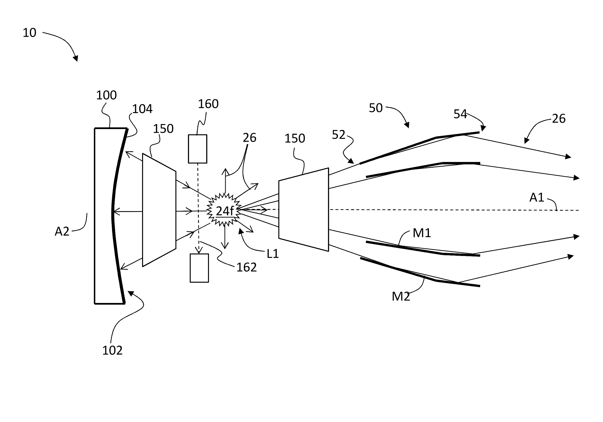
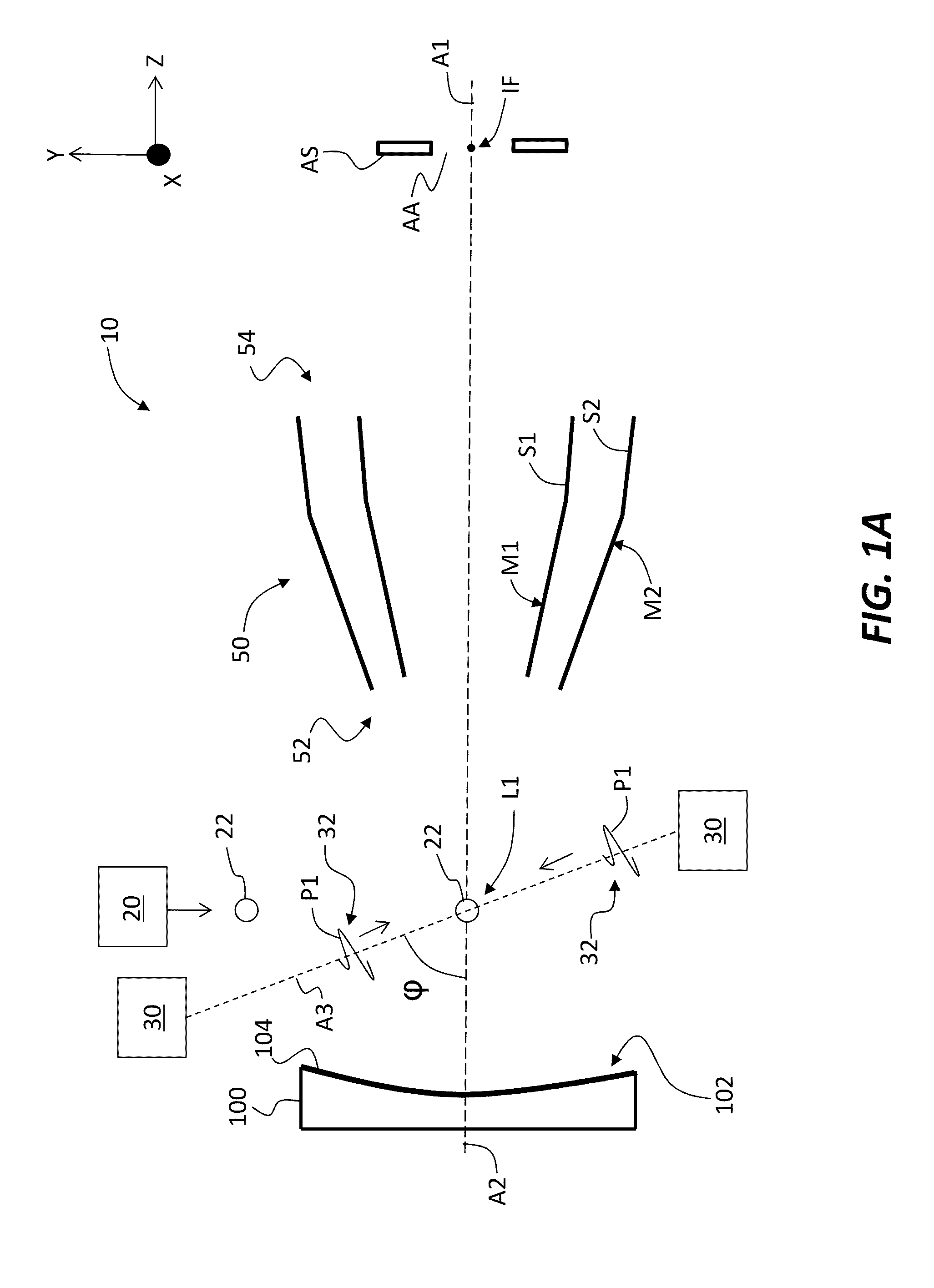
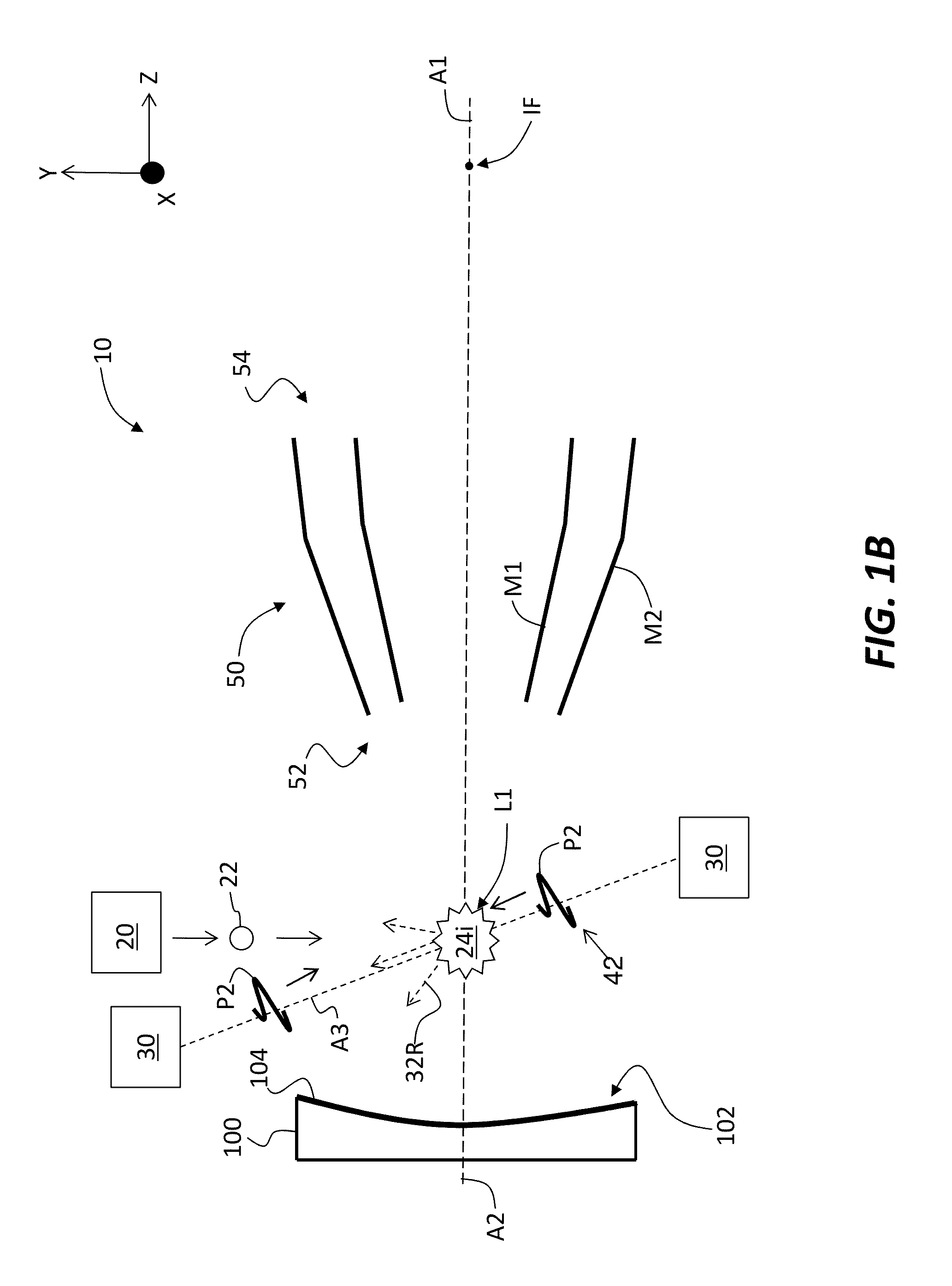
[0123]The disclosure relates to EUV lithography and in particular to SoCoMo configurations for use with EUV lithography systems, wherein the SoCoMos employ an LPP EUV radiation source, and a GIC. The SoCoMos have a variety of example configurations, as explained below.

Limiting Reflected IR Collection when Using Low-Mass Target

[0124]FIGS. 1A through 1D are schematic diagrams of an example embodiment of an MCC-LPP-GIC SoCoMo (“SoCoMo”) 10 that includes a GIC 50 and an optional MCC 100. The GIC 50 includes a central axis A1 and, in this example, two concentric GIC mirrors M1 and M2 shown in a cross-section. The GIC mirrors M1 and M2 have reflective surfaces S1 and S2 that include a grazing-incidence reflective coating, which in an example is formed from Ru. In an example, the reflective coating is sufficiently thick for GIC mirrors M1 and M2 to tolerate some erosion due to debris generated in the operation of the SoCoMo, as discussed below. Note that mirrors M1 and M2 are rotationally ...


PUM


Abstract

Source-collector modules for use with EUV lithography systems are disclosed, wherein the source-collector modules employ a laser-produced plasma EUV radiation source and a grazing-incidence collector. The EUV radiation source is generated by first forming an under-dense plasma, and then irradiating the under-dense plasma with infrared radiation of sufficient intensity to create a final EUV-emitting plasma. The grazing incidence collector can include a grating configured to prevent infrared radiation from reaching the intermediate focus. Use of debris mitigation devices preserves the longevity of operation of the source-collector modules.

Description

CLAIM OF PRIORITY[0001]This application claims the benefit of priority under 35 U.S.C. §119(e) of U.S. Provisional Application Ser. No. 61 / 597,744, filed on Feb. 11, 2012, which is incorporated by reference herein.FIELD[0002]The disclosure relates to extreme ultraviolet (EUV) lithography and in particular to source-collector modules for use with EUV lithography systems, wherein the source-collector modules employ a laser-produced plasma EUV radiation source and a grazing-incidence collector mirror.BACKGROUND ART[0003]Extreme ultraviolet lithography (EUVL) involves using EUV radiation (typically 13.5 nm+ / −2%) generated by an EUV radiation source to irradiate a reflective patterned mask to transfer the pattern onto a photoresist layer supported by a silicon wafer. The use of the small wavelengths associated with EUV radiation allows for the minimum feature size of the imaged pattern to also be small, i.e., as small as 15 nm and below.[0004]There has been a significant effort to create...

Claims


Application Information

Patent Timeline
Patent Type & Authority Patents(United States)
IPC IPC(8): G02B27/42H05G2/00G21K1/06G02B19/00G02B5/20
CPCG03F7/70166G03F7/70916G02B5/203G03F7/70575H05G2/005H05G2/008G02B27/425G21K2201/06G03F7/70033G21K2201/064G03F7/70316G21K1/067G02B19/0095
Inventor CEGLIO, NATALE M.STEARNS, DANIELKOOLS, JACQUESVALSECCHI, GIUSEPPEZOCCHI, FABIOBINDA, RICCARDO
Owner MEDIA LARIO SRL
Why Eureka
Try Eureka