Optical fibre

a technology of optical fibres and fibers, applied in the field of optical fibres, can solve the problems of inability to transpose, difficult manipulation, and large device weight, and achieve the effects of maximizing fluorescence collection, and optimizing the emission of high-power fluxes

Active Publication Date: 2020-07-30
CENT NAT DE LA RECHERCHE SCI +1
View PDF0 Cites 5 Cited by
  • Summary
  • Abstract
  • Description
  • Claims
  • Application Information

AI Technical Summary

Benefits of technology

[0072]Advantageously, the dimensions and characteristics of the different embodiments of the optical fibre according to the invention make it possible both to maximize the high-power flux and to maximize the collection of fluorescence. The invention thus optimizes the emission of a high-power flux associated with a collection of fluorescence.
[0073]Another advantage of an optical fibre according to the invention is to make it possible to allow the high-power treatment laser beam to be routed in a secure, flexible and practical manner.

Problems solved by technology

In contrast, two-photon microscopy is, a priori, an in vitro imaging instrument and thus cannot currently be transposed to an endoscopic instrument due to the dimension thereof.
However, such a device is particularly bulky and thus difficult to manipulate.
This represents a problem in particular for fine positioning of the laser with respect to the area to be explored or to be operated on.
Solid optical fibres are simpler to use but they have a damage threshold that is too low with respect to the pulse energies emitted by the ultrafast lasers.
In addition, their high dispersion and / or optical nonlinearity have the effect of distorting the temporal integrity of the pulse emitted.
However, the two types of guiding necessary have specific, even incompatible, structural constraints.

Method used


Image

  • Optical fibre
  • Optical fibre
  • Optical fibre

Examples


Embodiment Construction

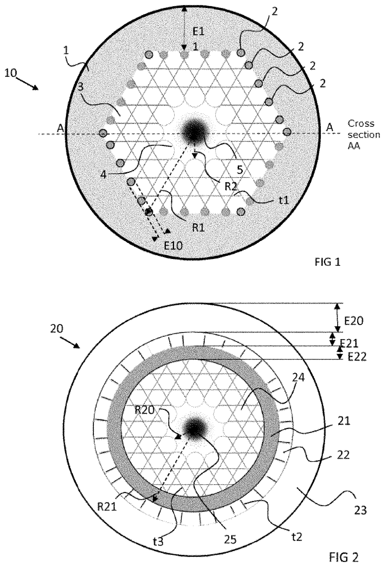
[0085]The invention is incorporated into an endoscope allowing both a fluorescent medical imaging by laser excitation and a cellular ablation by athermal laser ablation, all in a compact element. Advantageously, these two functions are borne by one and the same optical fibre. This optical fibre has the feature of allowing guiding by an inhibited coupling mechanism and by a total internal reflection mechanism, also called TIR. Guiding by inhibited coupling, IC, is based on a significant reduction in the guided mode optical integral in the core of the fibre and cladding modes. Unlike guiding by TIR or by band gap, guiding by IC does not require total absence of cladding modes at the effective index and guide frequency. In fact, the guided mode in the fibres guiding by IC is based on a reduction in its spatial overlap with the silica of the cladding and on a significant asymmetry of the transverse component between the field of the core and that of the cladding. In algebraic terms, the...


PUM

PropertyMeasurementUnit
thicknessaaaaaaaaaa
thicknessaaaaaaaaaa
thicknessaaaaaaaaaa

Abstract

An optical fibre for an ultrafast laser endoscope including at least the following structures: a hollow core, the periphery of which has an order of symmetry of at least six when considering axes of symmetry passing through the centre of the core and through the centre of convex shapes, seen from the centre of the core, the convex shapes at least partly making up the periphery of the core; an intermediate layer of cellular structure surrounding the core; a lightconducting peripheral structure surrounding the intermediate layer of cellular structure; and an outer sheath surrounding the light-conducting peripheral structure. A particular advantage of the optical fibre is that it optimizes the emission of a high-power flux associated with fluorescence collection.

Description

TECHNICAL FIELD[0001]The invention relates to the field of optical fibres and in particular that of optical fibres for an ultrafast laser endoscope.[0002]Endoscopy is a method for medical or industrial exploration or imaging which makes it possible in particular to view the interior of to channels or cavities that are inaccessible to the human eye. Conventionally, in medical endoscopy, the endoscope consists of an optical tube comprising an illumination coupled with a camera. An aim of endoscopy is to be able to carry out in situ imaging to be able to perform a diagnosis.[0003]In certain, in particular medical, and more particularly surgical, applications, the endoscope can be coupled with a tool, for example a cutting tool or a tool suitable for another treatment of cellular tissues. The tool can be borne by the optical tube of the endoscope. The endoscope thus makes it possible to perform an in situ operation.State of the Art—Description of the Technical Problem[0004]In the partic...

Claims


Application Information

Patent Timeline
Patent Type & Authority Applications(United States)
IPC IPC(8): G02B23/24A61B1/04G02B6/02A61B18/22
CPCA61B2018/00577A61B2018/2227A61B18/22A61B1/043G02B23/2469G02B6/02338G02B6/02328A61B1/07G02F1/365G02B6/02347G02B6/032G01N2021/6484A61B1/00167G01N21/6456A61B2017/00057A61B2018/2211G02B23/26C03B37/0122C03B2203/42C03B2203/14C03B2203/16
Inventor BENABID, ABDEL FETAH
Owner CENT NAT DE LA RECHERCHE SCI
Why Eureka
Try Eureka