
Compact construction vehicle with improved mobility

a construction vehicle and mobility technology, applied in the direction of steering gears, non-deflectable wheel steering, power driven steering, etc., can solve the problems of difficult maneuverability of inability to work in confined work space, and inability to maneuver even compact skid steer loaders in this manner. , to achieve the effect of improving traction and stability, easy control

Inactive Publication Date: 2007-10-18
COLTSON W CRAIG +1
View PDF4 Cites 53 Cited by
  • Summary
  • Abstract
  • Description
  • Claims
  • Application Information

AI Technical Summary

Benefits of technology

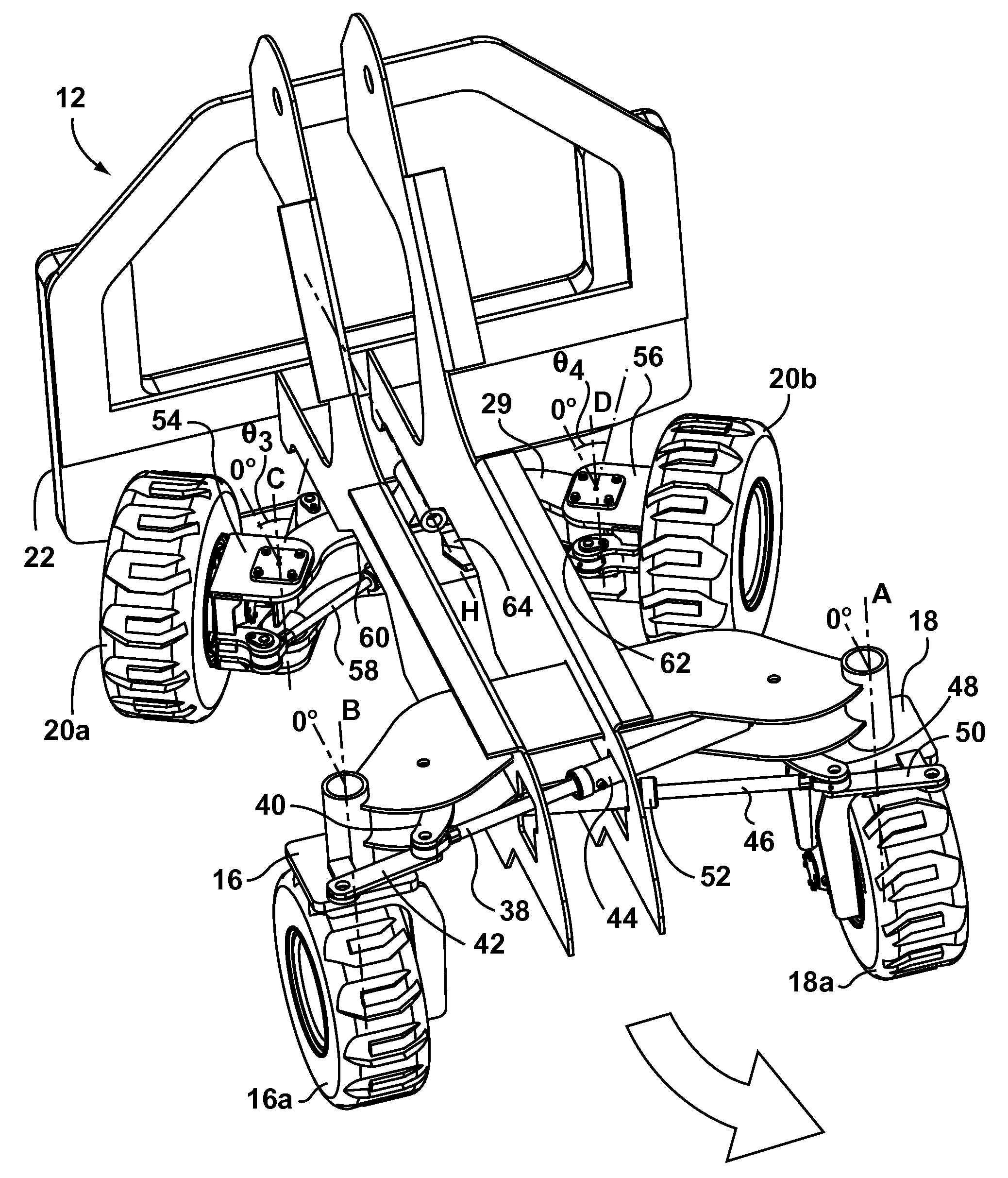
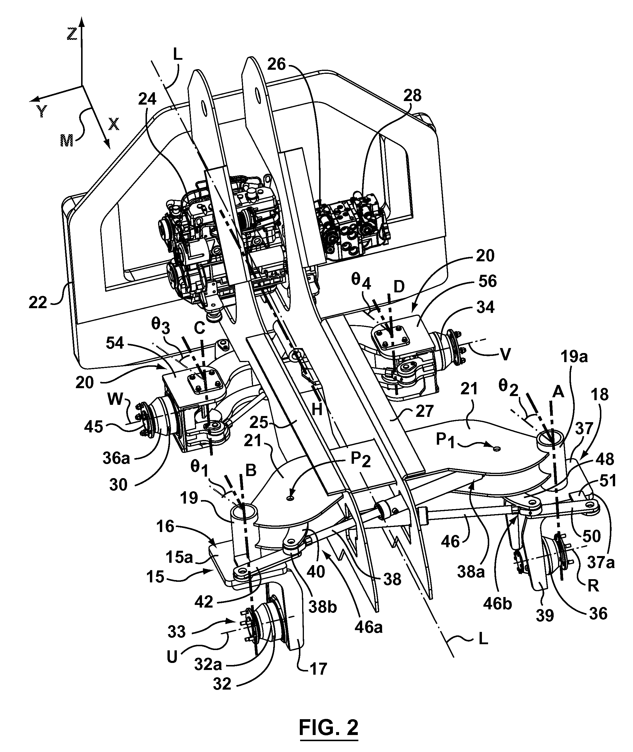
[0027]In some embodiments, the ground-engaging structures located on the front right and front left of the vehicle are coupled to the vehicle chassis in a rigid manner without any shocks or suspension system. This rigid configuration tends to provide improved stability of the vehicle when the vehicle is subjected to uneven loads. In other embodiments, the ground engaging structures can be coupled to the vehicle chassis by a suspension system, which may include a passive or active spring-damper suspension apparatus, which may provide the operator with a smoother ride and finer control over the vehicle operation, particularly when in use on uneven terrain.
[0028]In some embodiments, the distance between the steering pivot points (e.g. the axis about which each of the ground-engaging structures pivots) on the front right and front left ground-engaging structures has been maximized within the limits of the vehicle size in order to further enhance vehicle stability.
[0030]According to some embodiments, during use, the rear assembly can pivot with respect to the vehicle pivot point when the vehicle is traveling over uneven terrain, which helps to keep the wheels on the rear of the vehicle in constant contact with the ground. This tends to provide improved traction and stability when compared to prior art skid steer loaders because all four wheels on the vehicle tend to stay in contact with the terrain, even when the vehicle travels over uneven terrain. During operation of the skid steer vehicle, the speed and direction of the hydraulic wheel drive motors on the left side of the vehicle and on the right side of the vehicle are independent, but can preferably be easily controlled by the operator using the control devices, including the joystick and an operator steering mode switch. The inputs from the operator are provided to the electronic microcontroller, which contains a propulsion algorithm and controls the hydraulic hydrostatic pumps accordingly.
[0031]In some embodiments, the electronic microcontroller will provide the operator with the ability to select a variety of different steering modes or configurations. Within each distinct steering mode, the operator will have the ability to manipulate the pivotal position of each of the wheels within a predetermined pivotal range through the use of the control devices, including the joystick.

Problems solved by technology

While the dual loader arm configuration provides the skid steer loader the ability to dig and load, the extent to which the work implement can be utilized forwardly of the front of the vehicle is limited to the reach afforded by the fixed length loader arms.
While in some situations there is adequate room in the work area to easily maneuver the vehicle as needed, in many cases the work area is sufficiently confined that it becomes difficult to maneuver even compact skid steer loaders as needed.
However, turning in this manner is not always desirable for working in a confined work space, as the resulting turning radius can be quite large relative to the size of the vehicle.
As a result, it becomes difficult using this type of steering to maneuver the vehicle as desired to properly position the work implement.
However, skid steer vehicles driven in either steering mode still have a number of undesirable characteristics.
Most notably, the action of the wheels rotating in opposite directions can impart significant skidding stresses at the interface between the wheels of the vehicle and the ground surface on which the vehicle is moving.
These skidding stresses tend to tear the terrain over which the vehicle travels or result in increased wear on the wheels.
For instance, when a skid steer vehicle is used on soft surfaces that are common on construction sites (such as grass or muddy fields), the surfaces can quickly become torn up.
Any grass or other organic matter contacted by the wheels of a skid steer vehicle tends to be rapidly destroyed.
If the vehicle moves repeatedly in one particular area, this can also result in the formation of large ruts caused by the action of the tires.
The overall result is a generally undesirable amount of damage to property.
Furthermore, when used on harder surfaces, such as asphalt or concrete, rotating the wheels in opposite directions or “skidding” of the wheels can cause increased rates of wear to the tires on the vehicle, which can result in poor performance and increased operating costs.
One further problem presented by conventional skid steer vehicles relates to their performance on uneven terrain.
While this provides generally acceptable performance characteristics when the vehicle is used on even ground, when the skid steer vehicle is used on uneven terrain, one wheel of the vehicle tends to lift off the ground and lose traction.
This can lead to instability during use of the skid steer, which is dangerous when the operator is using the work implement, and also makes the skid steer loader more difficult to carefully maneuver.
Furthermore, this problem tends to aggravate the damage to the terrain since only three of the four drive wheels may be in contact with the ground.
The ground disturbance problems associated with the use of skid steer vehicles on soft ground, the wear problems associated with their use on hard surfaces and the loss of vehicle traction on uneven terrain tends to limit the use of skid steer vehicles to construction sites and other locations where damage to the ground is permissible and where the terrain is relatively even.
Furthermore, the limited reach afforded by the fixed length loader arms has precluded their use where it is difficult or impossible to maneuver the vehicle close enough to the desired work position.

Method used


Image

  • Compact construction vehicle with improved mobility
  • Compact construction vehicle with improved mobility
  • Compact construction vehicle with improved mobility

Examples


Embodiment Construction

[0054]It will be appreciated that for simplicity and clarity of illustration, where considered appropriate, reference numerals may be repeated among the figures to indicate corresponding or analogous elements or steps. In addition, numerous specific details are set forth in order to provide a thorough understanding of the exemplary embodiments described herein. However, it will be understood by those of ordinary skill in the art that the embodiments described herein may be practiced without these specific details. In other instances, well-known methods, procedures and components have not been described in detail so as not to obscure the embodiments described herein. Furthermore, this description is not to be considered as limiting the scope of the embodiments described herein in any way, but rather as merely describing the implementation of the various embodiments described herein.

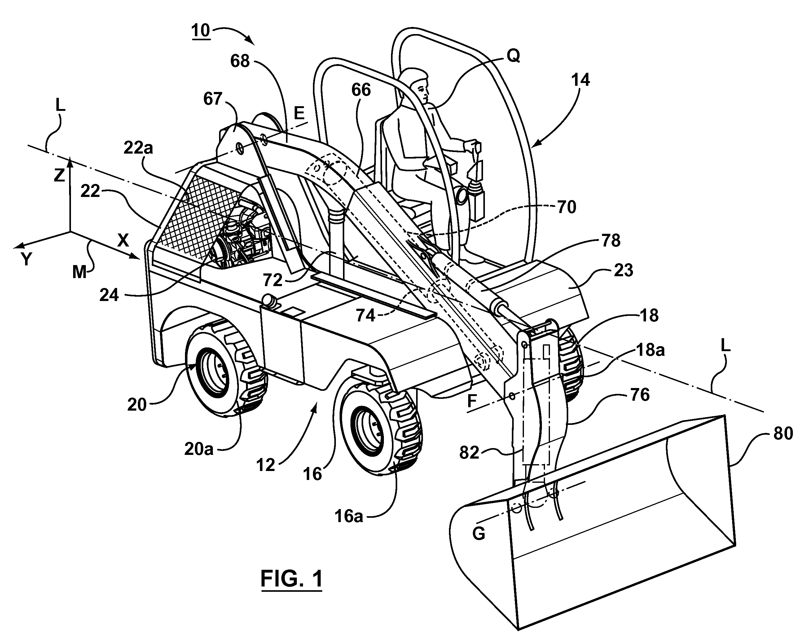
[0055]Referring now to FIGS. 1 to 4A generally, illustrated therein is compact loading vehicle 10 made ...


PUM


Abstract

A loader type construction vehicle includes a chassis having a longitudinal axis, a plurality of wheeled ground-engaging structures pivotally coupled to the chassis, and a steering control system. Each of the plurality of ground-engaging structures includes a wheel pivotable about a steering axis and drivable about a drive axis, wherein each of the wheeled ground-engaging structures is shaped and configured so that the wheel of each of the ground-engaging structures can be pivoted from a first angular position in which the drive axis is perpendicular to the longitudinal axis, to a second angular position that is at least 90° degrees from the first angular position. The steering control system is operatively connected to each of the ground engaging structures for pivoting the wheel of each of the ground-engaging structures about the steering axis. The steering system may be operable to selectively configure the ground engaging structures into a plurality of different steering configurations, such as crab steering and side steering. The loader vehicle may include a telescopic loader arm.

Description

RELATED APPLICATIONS[0001]This application claims priority from U.S. provisional application Ser. No. 60 / 791,452.FIELD OF THE INVENTION[0002]The present invention relates generally to compact construction vehicles and more particularly to the mobility and working reach of compact loader type construction vehicles.BACKGROUND OF THE INVENTION[0003]Compact loader type construction vehicles are common and popular vehicles used in the construction industry. One of the most common variations is the compact skid steer loader.[0004]Skid steer loaders were first developed approximately 30 to 40 years ago to fill the requirement for a highly maneuverable construction vehicle capable of digging, lifting, transporting and loading earth, gravel and other construction materials. Compact skid steer loaders are typically small with a length of approximately 10-12 feet, and a narrower width.[0005]The most common form of compact skid steer loaders have two fixed length loader arms mounted on the vehi...

Claims


Application Information

Patent Timeline
IPC IPC(8): B62D11/24
CPCB62D7/1509B62D9/002B62D11/003B62D61/00E02F9/2253E02F3/3402E02F9/02E02F9/0808E02F9/225E02F3/283
Inventor COLTSON, W. CRAIGALBU, IOAN SORIN
Owner COLTSON W CRAIG
Learn More