Optical measuring device
a measuring device and optical technology, applied in the direction of measurement devices, optical radiation measurement, instruments, etc., can solve the problems of increased measurement errors and likely causes of measurement errors, and achieve the effects of reducing measurement errors, high output, and high snr
- Summary
- Abstract
- Description
- Claims
- Application Information
AI Technical Summary
Benefits of technology
Problems solved by technology
Method used
Image
Examples
embodiment 1
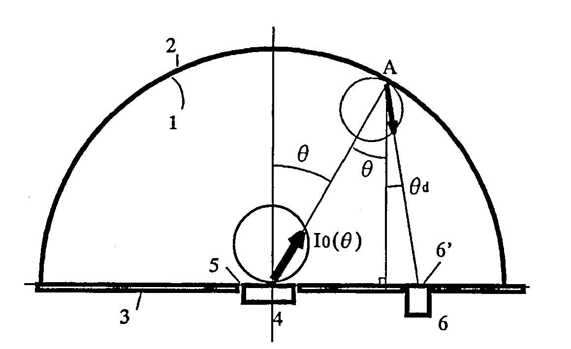
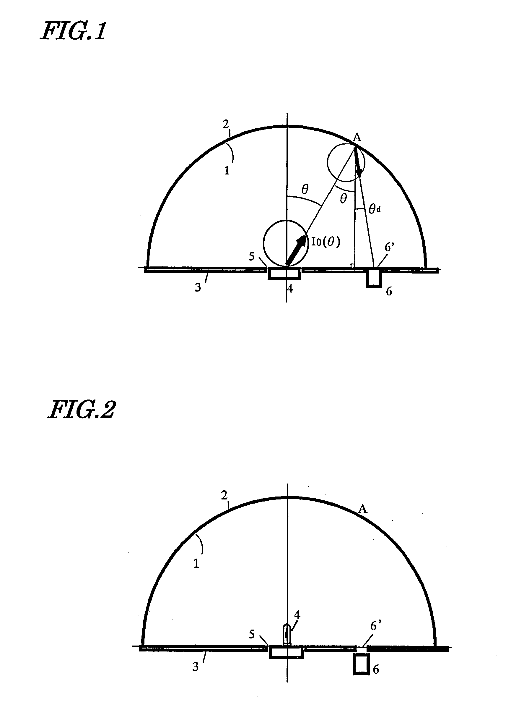
[0057]A first preferred embodiment of an optical measuring device according to the present invention will be described with reference to FIG. 1.
[0058]The optical measuring device of this preferred embodiment is a total luminous flux measuring device that includes an integrating hemisphere 2, of which the inner wall surface functions as a light diffuse reflective surface 1, and a plane mirror 3 to close the opening of the integrating hemisphere 2. The light diffuse reflective surface 1 is formed by either coating the inner surface of the integrating hemisphere 2 with a diffusive material that diffuses the radiation to be measured or processing the inner surface of the integrating hemisphere 2. The plane mirror 3 has a central opening that functions as either a light entering window or a light source fitting hole 5 and an observation window 6′ that enables a photodetector 6 to take measurements. The center of radius of curvature of the hemisphere 2 is defined within the central openin...
embodiment 2
[0078]A second preferred embodiment of an optical measuring device according to the present invention will be described with reference to FIG. 2.
[0079]The photometer shown in FIG. 2 includes an integrating hemisphere 2, of which the inner wall surface functions as a light diffuse reflective surface 1, and a plane mirror 3, which is arranged so as to close the opening of the integrating hemisphere 2, including the center of curvature thereof. A light source 4, of which the total luminous flux should be measured, is fitted into a light source fitting window 5, which is arranged at the center of curvature of the integrating hemisphere 2 on the surface of the plane mirror 3. Meanwhile, a photodetector 6 is fitted into an observation window 6′ on the surface of the plane mirror 3 but is arranged such that the light source 4 is invisible to the photodetector 6.
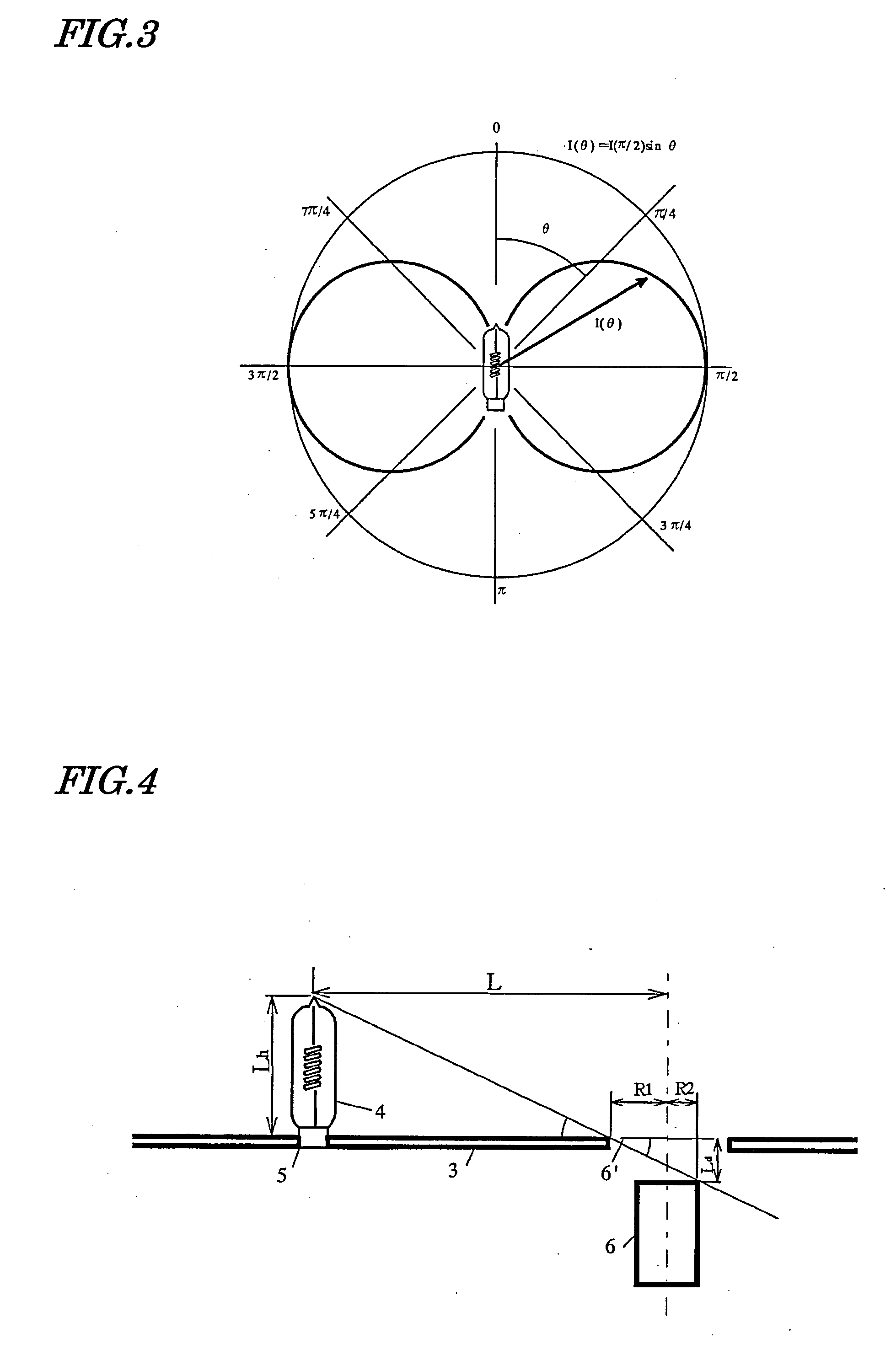
[0080]Next, the operating principle of the photometer of this preferred embodiment will be described.
[0081]The light source 4 of t...
embodiment 3
[0101]A third preferred embodiment of an optical measuring device according to the present invention will be described with reference to FIG. 5.
[0102]The device of this preferred embodiment (total luminous flux measuring device) includes an integrating hemisphere 2, of which the inner wall surface functions as a light diffuse reflective surface 1, and a plane mirror 3, which is arranged so as to close the opening of the integrating hemisphere 2, including the center of curvature thereof. A light source 4, of which the total luminous flux should be measured, is fitted into a light source fitting window 5, which is arranged at the center of curvature of the integrating hemisphere 2 on the surface of the plane mirror 3. In this preferred embodiment, a luminometer 8 measures the luminance at an infinitesimal surface element A on the inner wall of the integrating hemisphere 2 through an observation window 6′ on the plane mirror 3.
[0103]Next, the operating principle of the photometer of t...
PUM
 Abstract
Description
Claims
Application Information
 - R&D
- Intellectual Property
- Life Sciences
- Materials
- Tech Scout
- Unparalleled Data Quality
- Higher Quality Content
- 60% Fewer Hallucinations
Browse by: Latest US Patents, China's latest patents, Technical Efficacy Thesaurus, Application Domain, Technology Topic, Popular Technical Reports.
© 2025 PatSnap. All rights reserved.Legal|Privacy policy|Modern Slavery Act Transparency Statement|Sitemap|About US| Contact US: help@patsnap.com


