Optical resonator gyro with external cavity beam generator

a gyro and beam generator technology, applied in the field of rotating sensors, can solve the problems of reducing the accuracy of rotation rate detected by the gyro, false indication of rotation or inaccurate measurement of rotation rate, and difficulty in economically implementing frequency shifters and phase modulators

Active Publication Date: 2007-10-18
HONEYWELL INT INC
View PDF60 Cites 58 Cited by
  • Summary
  • Abstract
  • Description
  • Claims
  • Application Information

AI Technical Summary

Problems solved by technology

The frequency shifters and phase modulators may be difficult to economically implement particularly for smaller scale applications or implementations of the resonator gyro.
However, when using two or more tunable lasers for resonance detection, the relative frequency noise between such lasers is typically the greatest contributor to angle random walk (ARW) which decreases the rotation rate accuracy of detected by the resonator gyro.
In the RFOG, the glass material of the optical fiber may give rise to effects that shift the resonance frequencies of the CW and CCW paths and thus produce a false indication of rotation or inaccurate measurement of rotation rate.
Anomalies stemming from the glass medium that decrease the accuracy of the measurement of the rotational rate may be generated from a non-linear Kerr effect, stimulated Brillouin scattering, polarization errors, and Rayleigh backscatter errors.
These error mechanisms are also sensitive to the environment which, for example, gives rise to unwanted temperature sensitivity.
A reflective mirror may be used to circulate the counter-propagating light beams in the coil multiple times but this typically reduces the signal-to-noise ratio from losses generated at the transition from the mirror to the coil.
Polarization-induced errors may result from fiber couplers that incidentally couple light into a second polarization mode, either from one optical fiber to an adjacent optical fiber or within the same fiber.
Polarization-induced errors may severely limit the accuracy of the RFOG because determination of the resonance centers for each of the resonance frequencies of the CW and CCW beams directly affects the rotational rate measurement.
Rayleigh backscatter errors may be a source of drift rate in a resonator gyro.
Backscattered light from the glass within the fiber or from imperfections with the fiber can interfere with the circulating light beams and cause significant drift rate errors.
In addition to encountering error mechanisms that may affect accuracy, the conventional RFOG may be cost prohibitive for high volume production, particularly for a smaller scale RFOG.
For smaller scale applications, the cost associated with assembling the RFOG generally increases with the increased cost for miniaturizing each discrete component and aligning the miniaturized discrete optical components.

Method used


Image

  • Optical resonator gyro with external cavity beam generator
  • Optical resonator gyro with external cavity beam generator
  • Optical resonator gyro with external cavity beam generator

Examples


Embodiment Construction

[0019] The following detailed description of the invention is merely exemplary in nature and is not intended to limit the invention or the application and uses of the invention. Furthermore, there is no intention to be bound by any theory presented in the preceding background of the invention or the following detailed description of the invention.

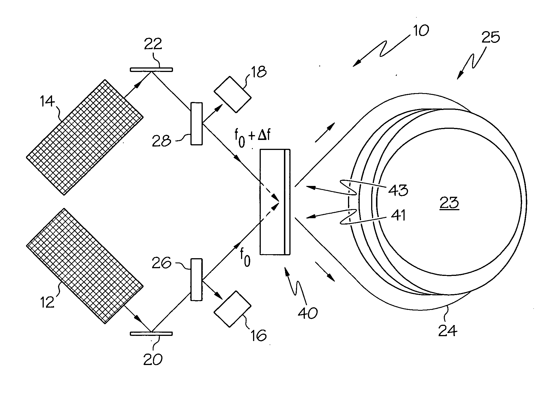
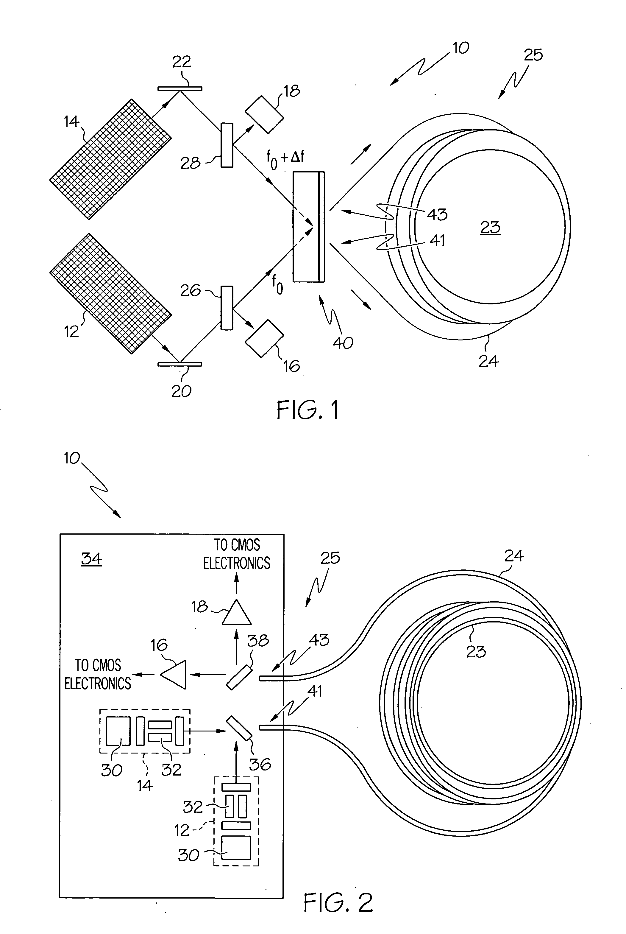
[0020] Referring now to the drawings, FIG. 1 is a block diagram of a resonator gyro 10 in accordance with an exemplary embodiment of the present invention. The resonator gyro 10 comprises first and second tunable light sources 12, 14 (e.g., tunable lasers) that synthesize light beams, respectively, a resonator 25 having a recirculator 40 that introduces the light beams into the resonator 25, and first and second photodetectors 16, 18 that receive first and second return beams from the resonator 25. The light beam produced by the first tunable laser 12 is tuned to a frequency f0, and the light beam produced by the second tunable laser 14 is...


PUM


Abstract

Methods and apparatus are provided for determining the rotational rate of an optical gyro. An optical gyro comprises at least one substrate, a multi-frequency light source (MFLS) mounted on the substrate, and a resonator coupled to the MFLS. The MFLS is configured to produce a first light beam having a first frequency and a second light beam having a second frequency and phase locked with the first light beam. The resonator comprises an optical fiber coil having a hollow core. The resonator is configured to circulate a portion of each of the first and second light beams through the hollow core. The portion of the first light beam propagates in a first counter-propagating direction, and the portion of the second light beam propagates in a second counter-propagating direction. A measured difference between the first and second frequencies indicates a frequency shift proportional to the rotation rate of the optical gyro.

Description

FIELD OF THE INVENTION [0001] The present invention generally relates to gyro systems, and more particularly relates to rotational sensors for use in navigation systems and attitude control. BACKGROUND OF THE INVENTION [0002] Gyros have been used to measure rotation rates or changes in angular velocity about an axis of rotation. A basic conventional fiber optic gyro (FOG) includes a light source, a beam generating device, and a coil of optical fiber coupled to the beam generating device that encircles an area. The beam generating device transmits light beams into the coil that propagate in a clockwise (CW) direction and a counter-clockwise (CCW) direction along the core of the optical fiber. Many FOGs utilize glass-based optical fibers that conduct light along a solid glass core of the fiber. The two counter-propagating (e.g., CW and CCW) beams experience different pathlengths while propagating around a rotating closed optical path, and the difference in the two pathlengths is propo...

Claims


Application Information

Patent Timeline
Patent Type & Authority Applications(United States)
IPC IPC(8): G01C19/72
CPCG01C19/727
Inventor HUGHES, GRENVILLESANDERS, GLEN A.STRANDJORD, LEE K.
Owner HONEYWELL INT INC
Why Eureka
Try Eureka