Method of Manufacturing Film-Speaker Using Piezoelectric Film and Sound Equipment with the Same

a piezoelectric film and film speaker technology, applied in the direction of transducer diaphragms, electrical transducers, plane diaphragms, etc., can solve the problems of inconvenient carrying along, limited design of conventional speakers, and inability to produce accurate wide-range frequencies, and achieve excellent high-frequency performance of film speakers

Inactive Publication Date: 2007-10-18
MIRAE PLASMA
View PDF5 Cites 8 Cited by
  • Summary
  • Abstract
  • Description
  • Claims
  • Application Information

AI Technical Summary

Benefits of technology

[0008] An object of the present invention is to provide a method of enhancing the adhesive property of the surface of a piezoelectric film in fabricating a film-speaker unit.
[0010] Another object of the present invention is to provide a sound equipment comprising a film-speaker, which is capable of producing accurately wide-range frequencies by combining a excellent high frequency performance of a film speaker and powerful reproduction in middle and low registers of a dynamic speaker. Technical Solution

Problems solved by technology

Moreover, the conventional speaker for a sound system has a fixed shape of a cube or cylinder type and is relatively heavy in weight.
Therefore, the conventional speaker is limited in design and inconvenient in carrying along.
In addition, it is difficult to manufacture a portable speaker for a portable sound source such as an MP3 player or CD player because the conventional speaker is mainly operated by electricity.
In view of sound, a conventional dynamic speaker is less powerful in a high-pitched tone and,thus, tends to convey distortedly the sound of string instruments or voice.
Therefore, a user may feel tired in listening the sound from the film speaker for a long time.
Moreover, the film-speaker has to employ an adaptor(direct current power device) because it requires a large amount of voltage.

Method used


Image

  • Method of Manufacturing Film-Speaker Using Piezoelectric Film and Sound Equipment with the Same
  • Method of Manufacturing Film-Speaker Using Piezoelectric Film and Sound Equipment with the Same
  • Method of Manufacturing Film-Speaker Using Piezoelectric Film and Sound Equipment with the Same

Examples


Embodiment Construction

[0019] Further objects and advantages of the invention can be more fully understood from the following detailed description taken in conjunction with the accompanying drawings.

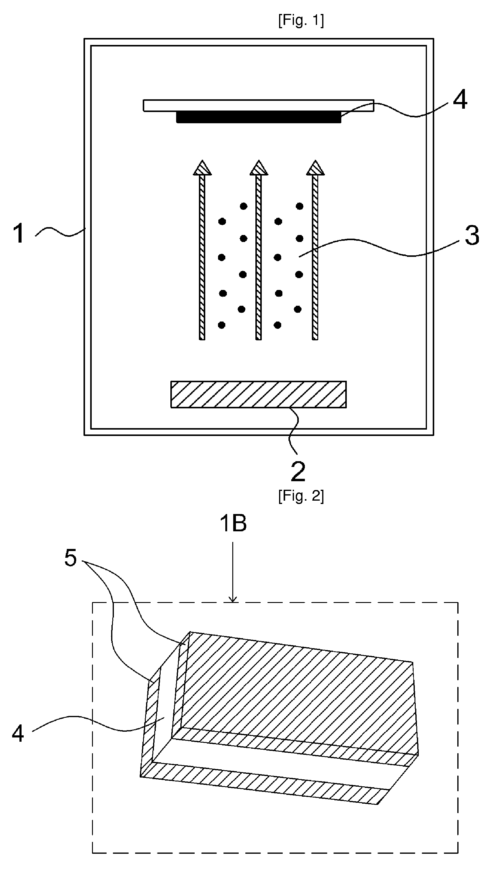
[0020]FIG. 1 is a drawing illustrating a method of surface reforming treatment to a piezoelectric film. To manufacture a film-speaker, conductive material has to be deposited on both surfaces of the piezoelectric film to form electrodes. The surface of the piezoelectric film has to be harshened through a surface reforming process using particles such as ions in order to help the conductive material to be easily deposited on the smooth surface of an ordinary piezoelectric film.

[0021] Referring to FIG. 1, a piezoelectric film (4) is first positioned in a vacuum chamber (1). The piezoelectric film may be selected from a group consisting of piezoelectric polymer such as polyvinylidenfluoride (hereinafter referred to as “PVDF”) and derivatives thereof, polymer blends including an additive such as HFP, and vinylid...


PUM


Abstract

A method of manufacturing a film-speaker using a piezoelectric material and a sound equipment with the film-speaker are disclosed. A sound equipment with a film-speaker comprises a film-speaker unit, a matching transformer connected with the film-speaker unit, an amplifier coupled with the matching transformer, and a power supply unit providing the amplifier with power The film-speaker unit includes a piezoelectric film and electrodes formed on both surfaces of the piezoelectric film. The surface of the piezoelectric film are reformed by irradiating ions with a predetermined energy under a vacuum state to increase an adhesive force. The electrodes are formed by depositing conductive material on both surfaces of the piezoelectric film. The sound equipment with a film-speaker further includes a condenser positioned between the film-speaker unit and the matching transformer, a dynamic speaker installed between the amplifier and the matching transformer, and a coil positioned between the amplifier and the dynamic speaker

Description

TECHNICAL FIELD [0001] The present invention relates to a method of manufacturing a film-speaker using a piezoelectric material and a sound equipment comprising the film-speaker, and, more particularly, a method manufacturing a thin film-speaker by increasing surface adhesive force of a thin piezoelectric film and a sound equipment comprising the thin film-speaker alone or both thin film-speaker and general loudspeaker. BACKGROUND ART [0002] A speaker is a device to generate a sound and has a variety of uses because it has to be necessarily employed to make a sound. Namely, the speaker is a necessary component used in every electronics from a toy to a telecommunication equipment as well as an audio equipment, a broadcasting equipment installed within a building or facilities, a television set, a radio set, and a telephone. [0003] A conventional speaker includes a circularly wound coil and a permanent magnet. When an electric current is applied to the circularly wound coil, induced e...

Claims


Application Information

Patent Timeline
Patent Type & Authority Applications(United States)
IPC IPC(8): H04R7/00H04R7/04H04R17/00
CPCH04R17/00H04R7/045
Inventor KIM, CHUL UNG
Owner MIRAE PLASMA
Why Eureka
Try Eureka