Continuous shearing edges made of brazed carbide grits for use on a tool

a technology of brazed carbide and shearing edge, which is applied in the direction of filing/raping tools, grinding devices, manufacturing tools, etc., can solve the problems of high cost, time-consuming, and difficult manufacturing and maintenance of special equipment, and achieves less friction caused heat, improved edge cutting structure, and less friction

a technology of brazed carbide and shearing edge, which is applied in the direction of filing/raping tools, grinding devices, manufacturing tools, etc., can solve the problems of high cost, time-consuming, and difficult manufacturing and maintenance of special equipment, and achieves less friction caused heat, improved edge cutting structure, and less friction

US20070243029A1Inactive Publication Date: 2007-10-18L R OLIVER

Image

  • Continuous shearing edges made of brazed carbide grits for use on a tool
  • Continuous shearing edges made of brazed carbide grits for use on a tool
  • Continuous shearing edges made of brazed carbide grits for use on a tool

Examples


Embodiment Construction

)

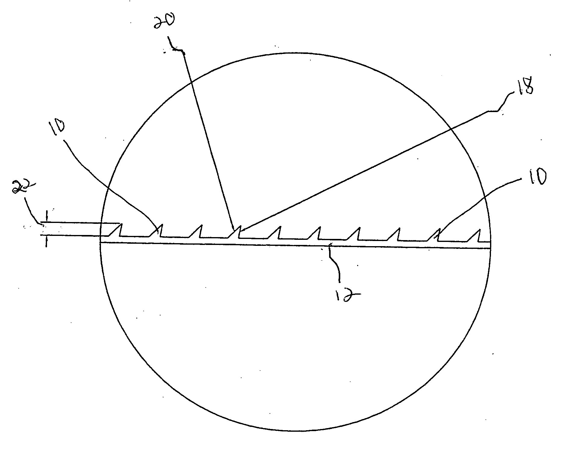
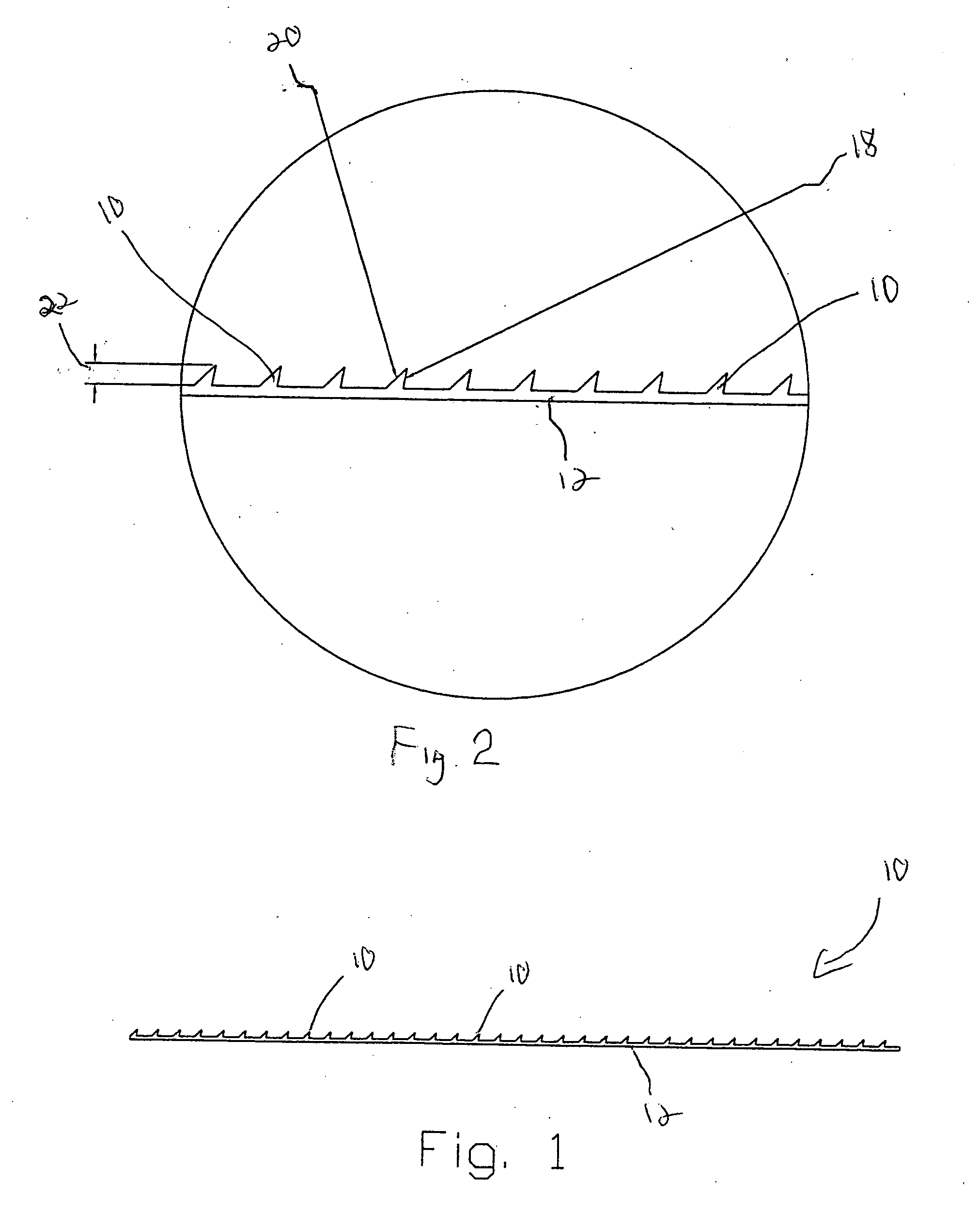
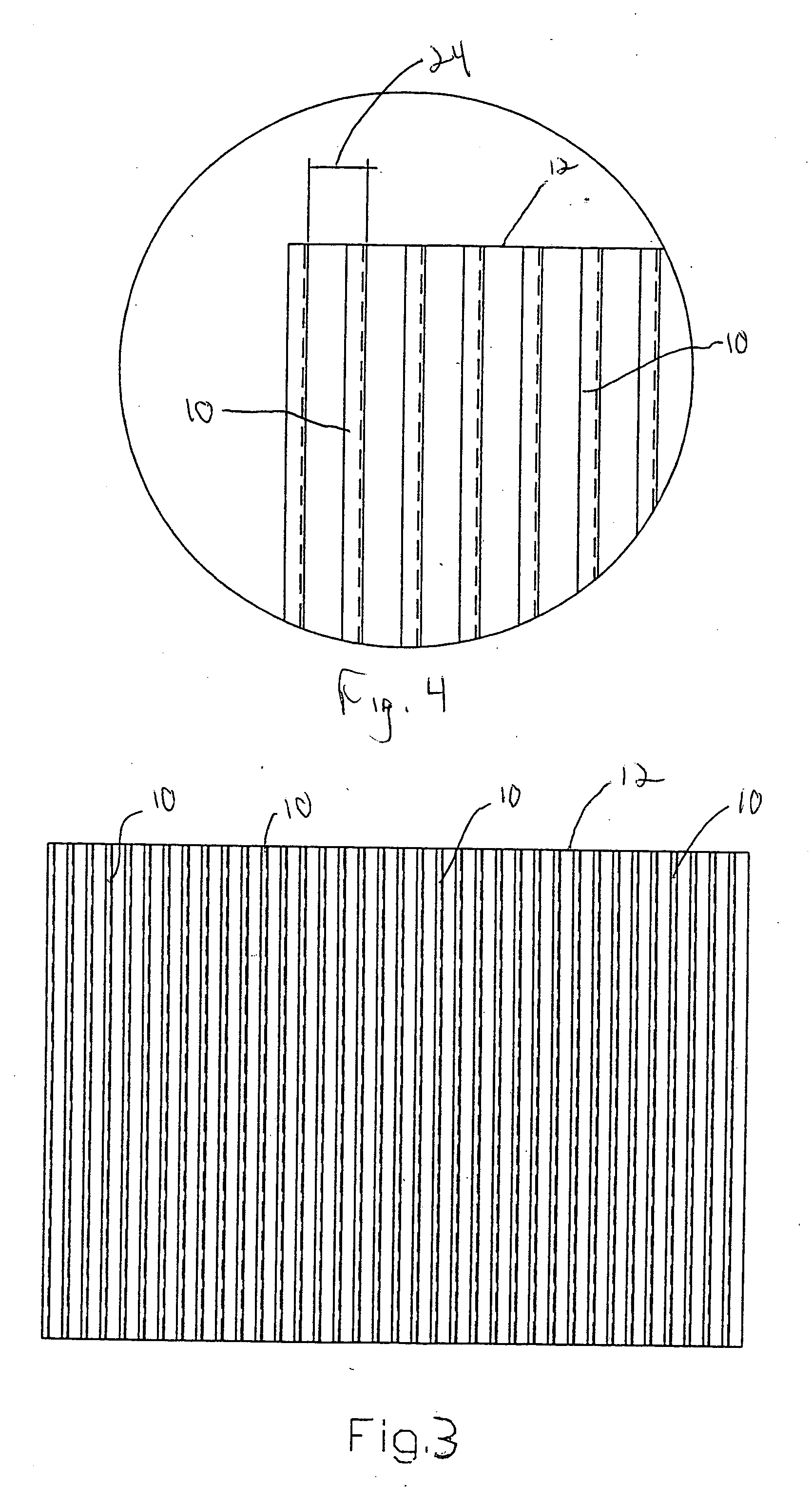
[0034] Referring to the drawings, the present invention of continuous shearing edges 10 composed of brazed carbide grits for use on a tool or grinding wheel 12 are shown. It should be noted that the continuous edges 10 are selectively attachable to a tool surface or a tool 12 such as a grinding wheel or the like. Applicant has developed various methods and apparatuses for connecting or molding teeth like structures to tool or surfaces and the present invention can be used with any of the Applicant's previous inventions and therefore, the Applicant hereby incorporates by reference prior U.S. Pat. Nos. RE 35,182; 4,916,869 and 6,821,196.

[0035] The edge structures 10 according to the present invention comprise pre-formed continuous or interrupted shearing machining edges that are composed of hard substance grits that are brazed together onto steel wheels or other tool or base members. The edges 10 may be interrupted by voids 14 between teeth 16 of the edges 10. The edges 10 have hard...


PUM

PropertyMeasurementUnit
rake angleaaaaaaaaaa
clearance angleaaaaaaaaaa
rake angleaaaaaaaaaa

Abstract

A preformed continuous or interrupted shearing machining edges that are composed of hard substance grits and are brazed together and to steel grinding wheels or other tool members. The parallel edges may be interrupted by voids between teeth of the edges. The edges have selectable edge rakes and clearance angles, edge tooth widths, edge spacing and mounting angles to the tool members or grinding wheel work surfaces.

Description

BACKGROUND OF THE INVENTION [0001] 1. Field of the Invention [0002] The present invention generally relates to abrasive grit structures used in the grinding and shaping of various material, and more particularly, relates to a continuous circular shearing edge composed of brazed carbide grits for use on a cutting and / or grinding tool for non metal materials and compositions. [0003] 2. Description of Related Art [0004] Abrasive grit tool structures have been known for numerous years. Generally, the abrasive grit tool structures include devices such as grinding wheels, hand tools, and the like which generally have an outer grit particle surface which is used to remove portions of a work piece for shaping and finishing a work piece. In many prior art structures, abrasive grits have been attached to tool surfaces by placing a single layer of grit particles on a tool form and then binding the grits to the tool by using a brazing metal or by an electro plating coating which grips the grit ...

Claims


Application Information

Patent Timeline
18 Oct 2007
Publication
US20070243029A1
IPC
B23D71/00
CPC
B23D71/025; B23D73/06; Y10T407/18; B24D18/00; B24B7/20
Inventors
OLIVER, LLOYD R.