Four point utility blade

a technology of utility blades and blades, applied in the field of utility blades, can solve the problems of wasting blades, reducing the service and reducing the use of individual blades, so as to maintain blade stability, feel and control during use, and prolong the life of individual blades

a technology of utility blades and blades, applied in the field of utility blades, can solve the problems of wasting blades, reducing the service and reducing the use of individual blades, so as to maintain blade stability, feel and control during use, and prolong the life of individual blades

US20070245574A1Active Publication Date: 2007-10-25BLACK & DECKER INC

Image

  • Four point utility blade
  • Four point utility blade
  • Four point utility blade

Examples


Embodiment Construction

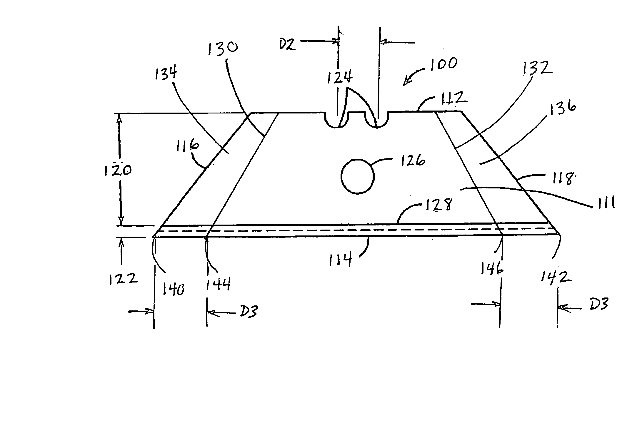
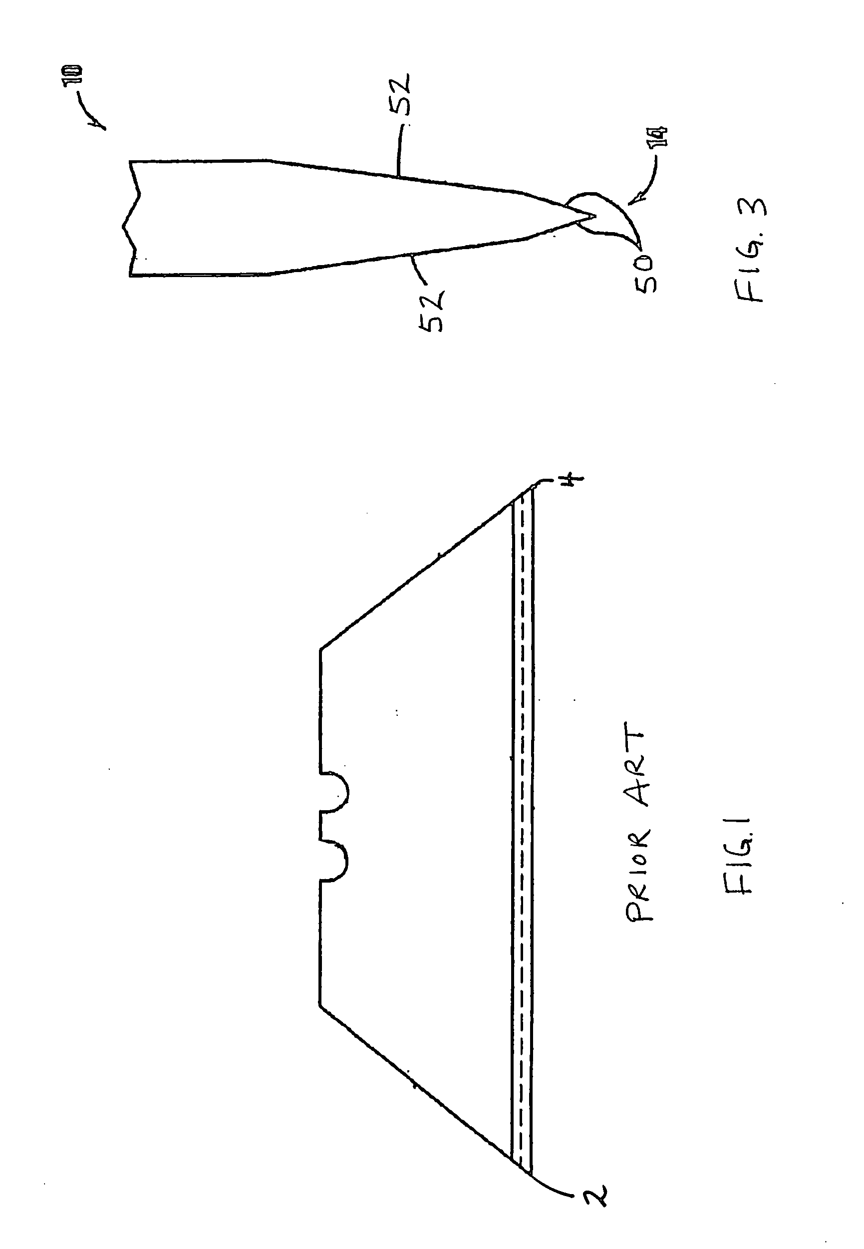
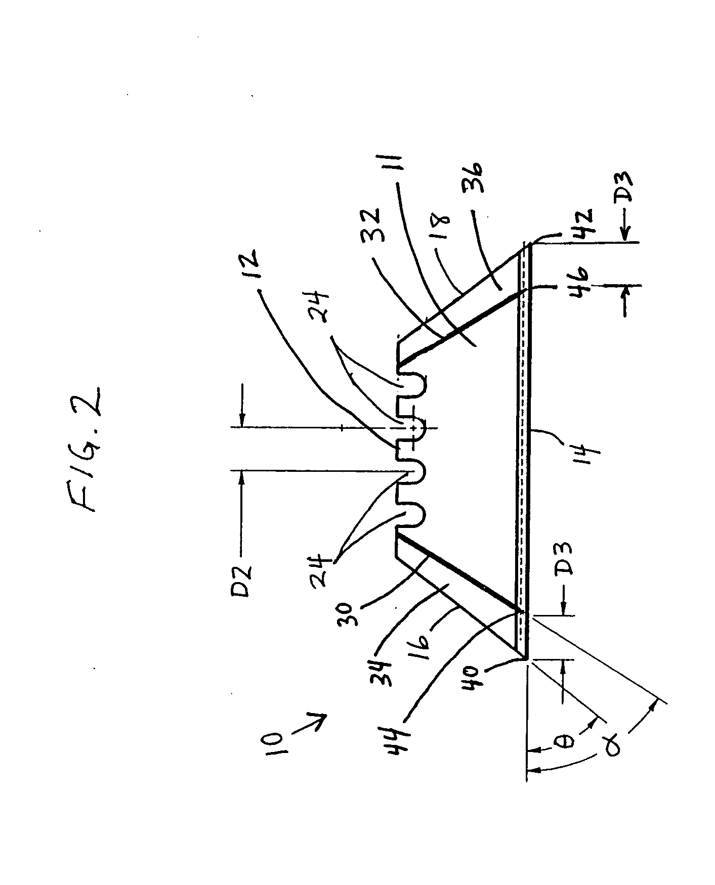
[0023] In FIGS. 2, 4 and 5, a four-point or snap trap utility knife blade herein described is indicated generally by the reference numeral 10. The blade is completely usable with conventional industry standard retractable and fixed blade utility knives that utilize conventional trapezoidal utility blades, but can also be used with additional utility knives and holders that are currently known or later become known. The utility knife blade 10 comprises a generally planar blade body 11 that defines a back edge 12, a cutting edge 14 located on an opposite side of the blade relative to the back edge, and two side edges 16, 18 located on opposite sides of the blade relative to each other and extending between the back and cutting edges of the blade 10. The intersection of each side edge 16,18 and the cutting edge 14 forms a pair of primary cutting points, first cutting point 40 and second cutting point 42 respectively, which are typically used for cutting and puncturing work pieces. In o...


PUM


Abstract

A utility blade for use with conventional retractable and fixed blade utility knives comprising a blade body having a generally trapezoidal configuration defined by a cutting edge, an opposite back edge, a pair of opposing side edges and a pair of cutting points defined by the points of intersection between the side edges and the cutting edge. The blade further defines a pair of score lines, each proximate to one of the side edges. The score lines enable the user to remove a dulled or damaged cutting point, which in turn provides the user with two additional cutting points defined by the points of intersection between the score lines and the cutting edge. Further, the blade is configured with one or more notches strategically located on the back edge of the blade, such that each cutting point can extend from the utility knife at approximately the same distance.

Description

FIELD OF THE INVENTION [0001] The present invention relates to utility knife blades and, more particularly, to conventional utility knife blades having one or more score lines that allow the user to snap off a dulled point in a relatively precise location, thereby providing the user with more than two useful cutting points. BACKGROUND [0002] Conventional utility knives having disposable utility blades are well known in the art. These knives have many industrial as well as home uses, such as for opening boxes, cutting cord, or carving wall board or wood. A typical utility knife has a plastic or metal handle with either a fixed or retractable utility blade mounted therein. When in use, the blade is positioned to extend outwardly from the handle, exposing the cutting edge and one of the cutting points of the blade. [0003] Utility knife blades come in a variety of shapes depending upon the intended use. As shown with reference to FIG. 1, a conventional utility blade has a generally trap...

Claims


Application Information

Patent Timeline
25 Oct 2007
Publication
US20070245574A1
IPC
B26B21/54
CPC
B26B9/00
Inventors
GREEN, MATTHEW C.