

Tire for an aircraft and method for producing the same
a pneumatic radial and aircraft technology, applied in the field of tires, can solve the problems of increased abrasion rate and bad appearance of tires, and achieve the effects of effectively eliminating the risk of separation, reducing the amount of zigzag bending in each bent strip, and effectively preventing the cut ends of the cords in the sub-belt layer
- Summary
- Abstract
- Description
- Claims
- Application Information
AI Technical Summary
Benefits of technology
Problems solved by technology
Method used
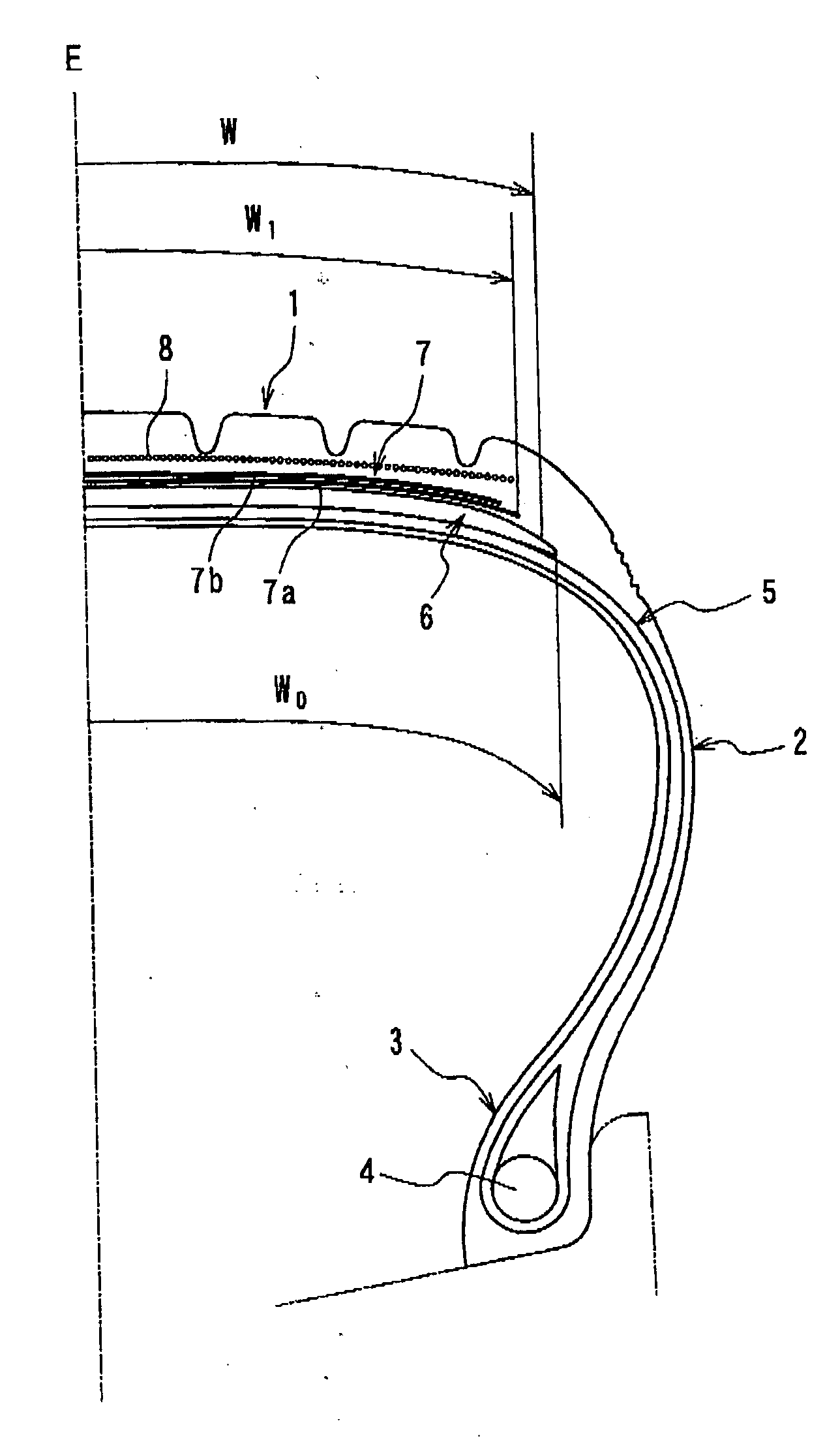
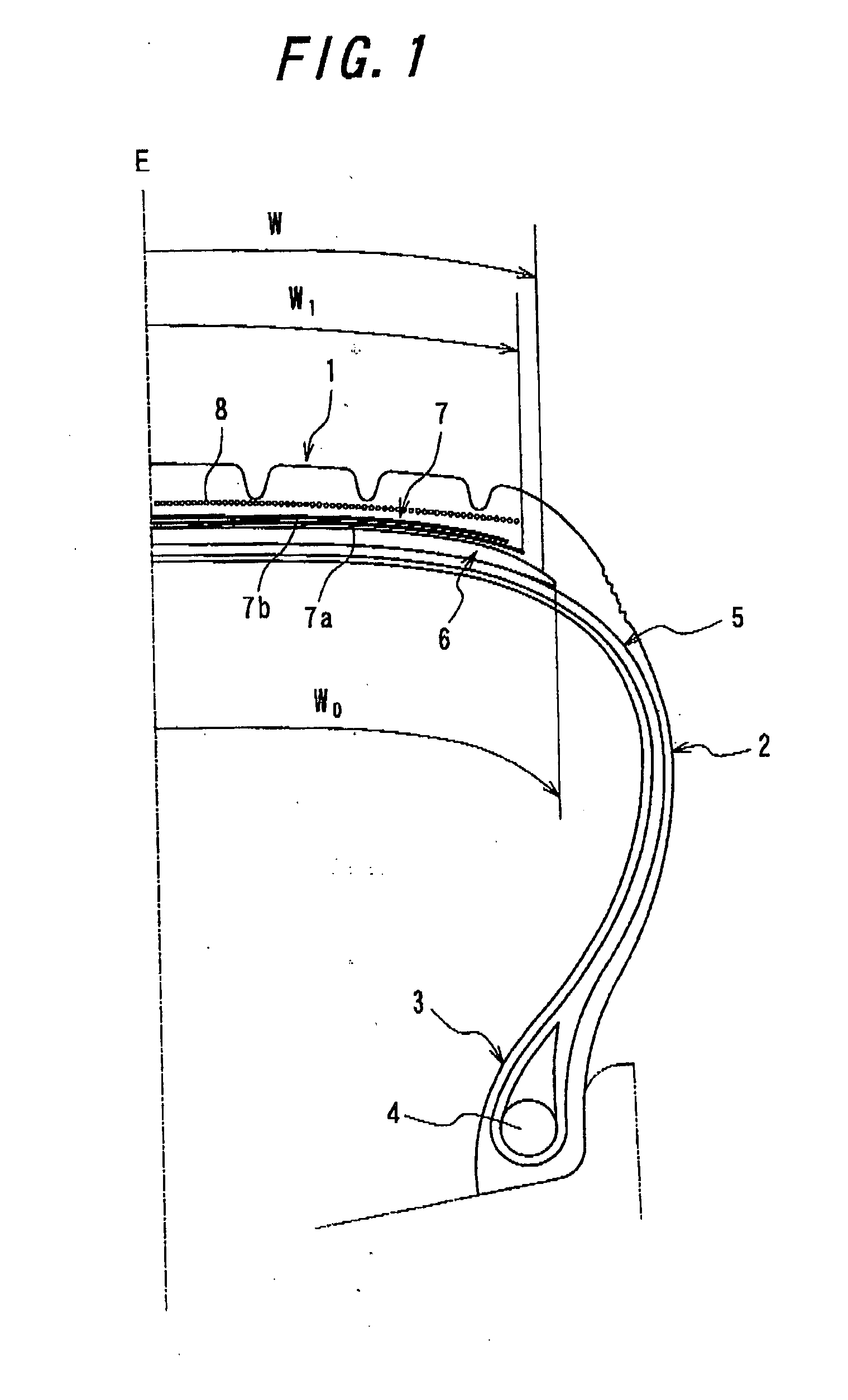
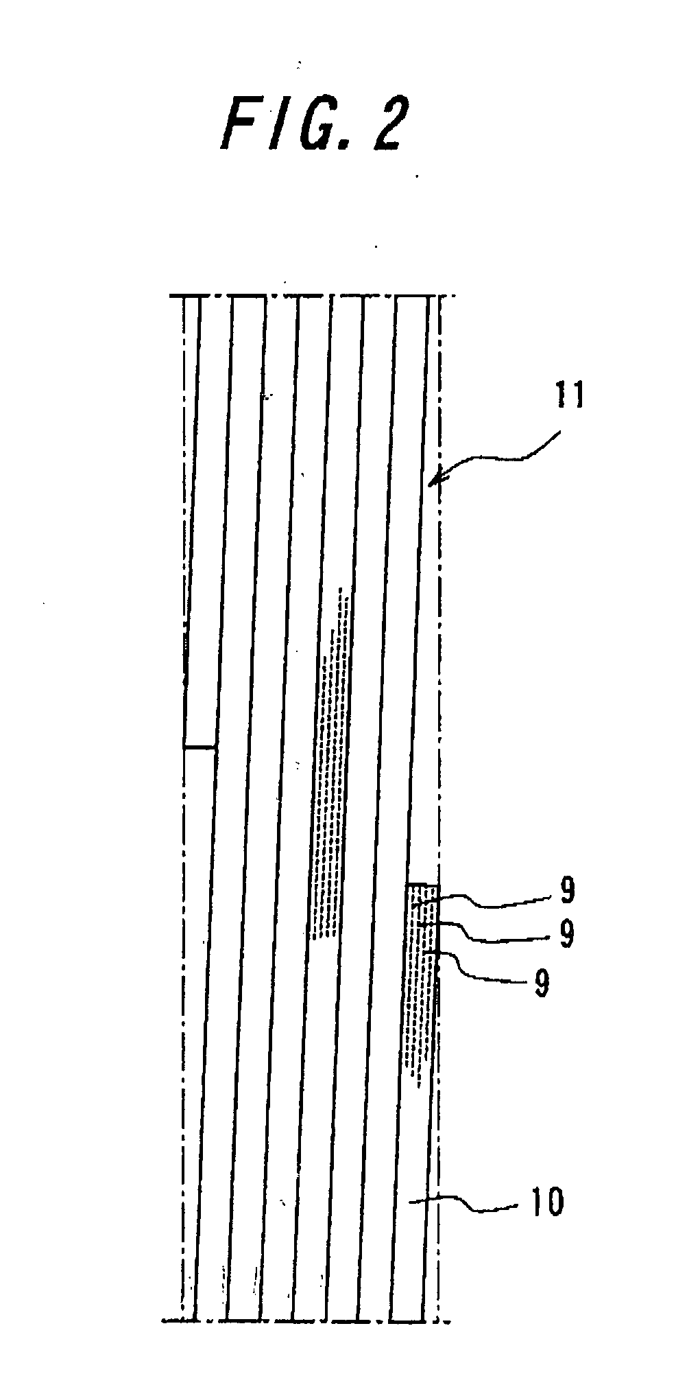
Image

Examples
example 1
[0044] Tires of this example having the above-mentioned structure and a size of 50×20.0 R22 34PR are experimentally manufactured and each of them is mounted on a rim having a size of 50×20.0 R22 and filled with air at an air pressure of 1620 kPa. A generation rate of standing wave of each tire is measured to obtain the result shown in Table 1. In this test, the generation rate of standing wave is measured when the tire is accelerated at a constant acceleration from a stopping state to a regulated velocity (378.2 km / h (235 mile / h)) for the tire size until a running distance reaches 3505.2 m (11500 ft) under a load corresponding to 187% of the maximum load capacity (27910 kg).
[0045] In Table 1, there is also shown the measurement result of a tire of Comparative Example by an index value, in which the width of the main belt is 100% of the tread contact width, the width of the sub belt is 90% of the tread contact width and the crossing angle of the organic fiber cords of the sub belt l...
example 2
[0048] Tires of this example having the same size as that mentioned above are experimentally manufactured and each of them is mounted on a rim and filled with air in the similar way to the above. A constant load corresponding to 80% of the maximum load capacity is applied to the tire and under the circumstances, the tire is rotated at constant velocity of 64.37 Km / h (40 mile / h) for 4 minutes, which is defined as one cycle. A running durability test is performed by repeating the cycles with an interval of 120 minutes between each cycle, and the running distance until failure due to separation between layers of the main belt and sub belt is generated is measured. The results are shown in Table 2 in index values. Other parameters of the tires of Examples and Comparative Example are also shown in Table 2.
TABLE 2CrossingWidth ofWidth ofAngle ofMain Belt (%)Sub Belt (%)Cord of SubRunning(vs. Contact(vs. ContactBelt LayerDurabilityWidth)Width)(degree)(index value)Tire of1009040105Example...
example 3
[0051] Tires of this example are mounted on a rim and filled with air in a similar way to tires described in Example 1. A load corresponding to the maximum load capacity is applied to each tire, and an abrasion resistance test is performed in which the tire is rotated at very low velocity (less than 25 mm / s) to measure abrasion workload (amount of slipping of the tread). The results are shown in Table 3 in index values.
TABLE 3CrossingWidth ofWidth ofAngle ofMain Belt (%)Sub Belt (%)Cord of SubAbrasion(vs. Contact(vs. ContactBelt LayerResistanceWidth)Width)(degree)(index value)Tire of1009040103Example10010511090103100105100906010710011011090107100110100909011010011511090110100115Tire of1009010100ComparativeExample
[0052] The Table 3, the larger index value means the better result with using the value of the tire of Comparative Example as control.
[0053] It is clear from the results of Table 3 the larger width of the main belt and the larger crossing angle of the cords of the sub bel...
PUM
| Property | Measurement | Unit |
|---|---|---|
| Fraction | aaaaa | aaaaa |
| Fraction | aaaaa | aaaaa |
| Fraction | aaaaa | aaaaa |
Abstract
Description
Claims
Application Information