
Confocal Scanning Holography Microscope

Active Publication Date: 2007-10-25
HERRING RODNEY
View PDF19 Cites 12 Cited by
  • Summary
  • Abstract
  • Description
  • Claims
  • Application Information

AI Technical Summary

Benefits of technology

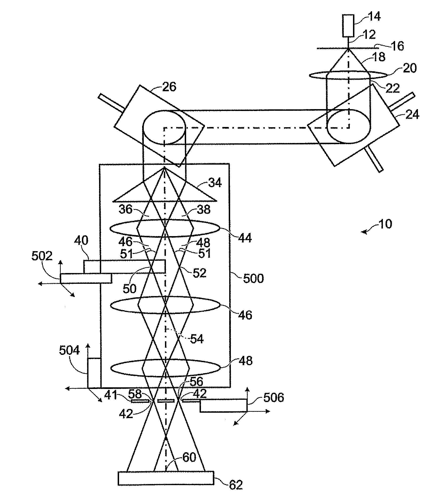
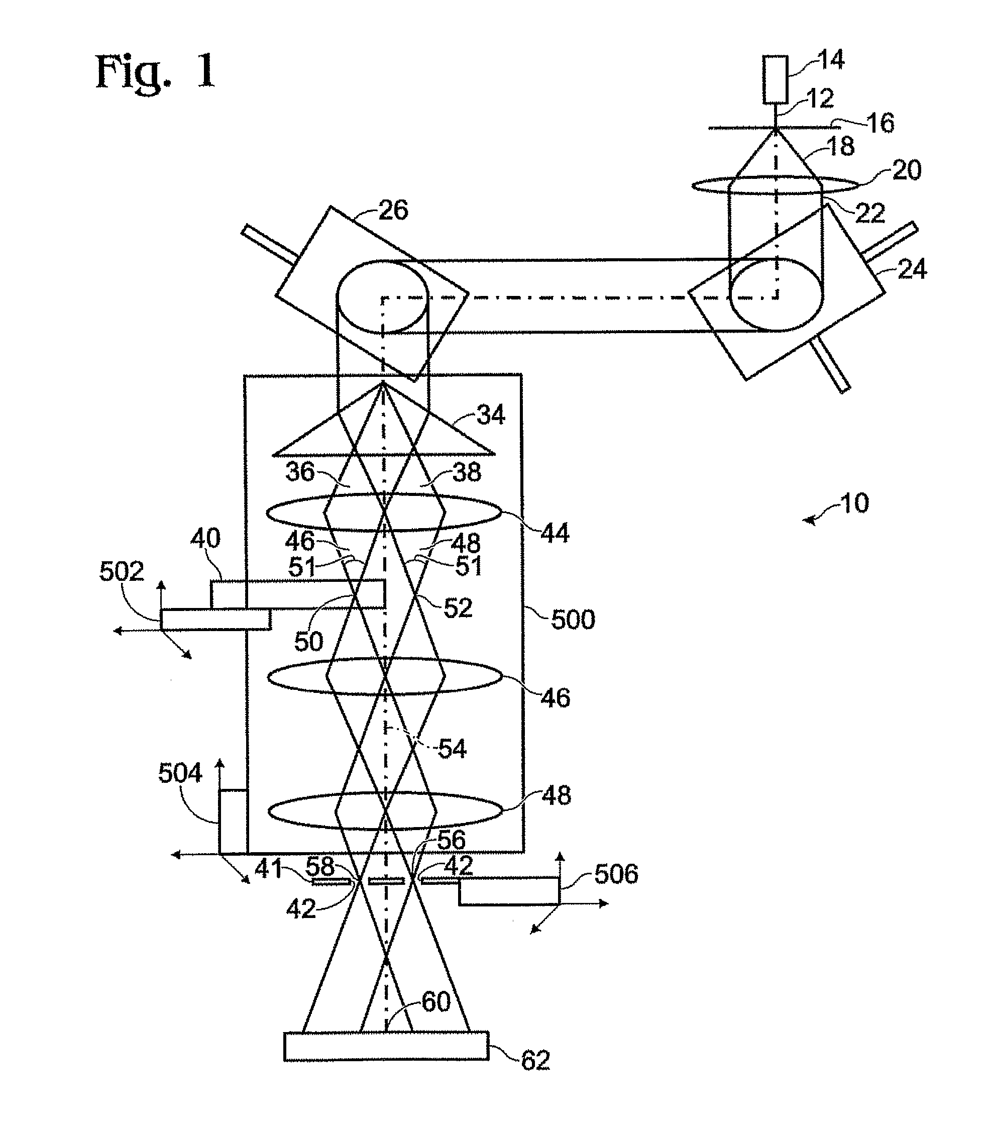
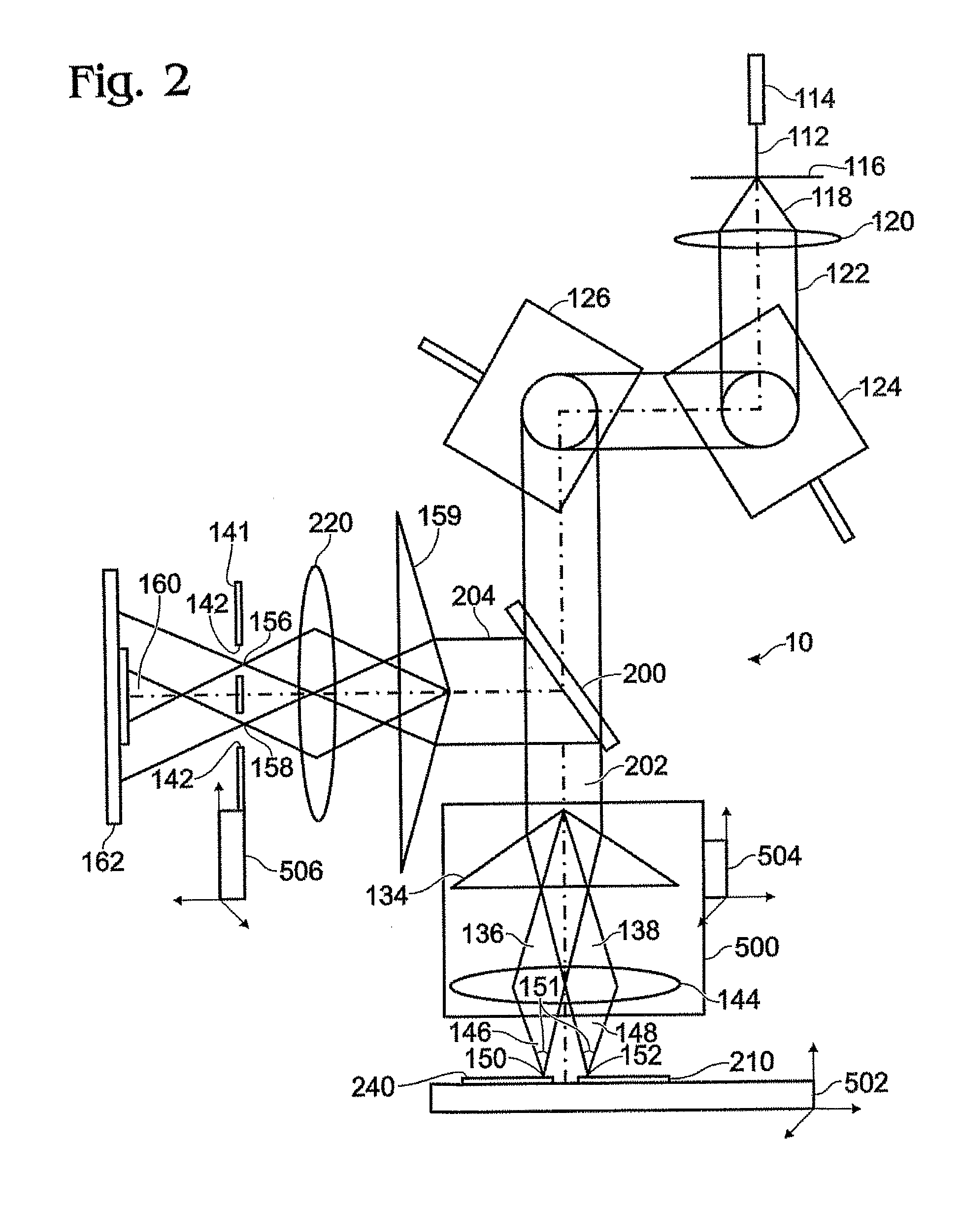
[0060] In another embodiment of the invention, a method for providing three dimensional information on an object comprising diverging a coherent beam from a coherent wavelength source, rastering the beam, splitting the beam into an object beam and a reference beam, focusing the resultant two beams, ensuring the length of the two beams are essentially equivalent, intercepting an object with said object beam at an object focal point, avoiding the object with the reference beam while having a reference focal point on the same plane as the object focal point, refocusing the two beams to second focal points that are confocal with the first focal points, limiting the beams and forming an interference pattern for detecting is provided.

Problems solved by technology

Hence, use of the above prior art limits the information that can be obtained.
An additional disadvantage of a number of diagnostic imaging techniques such as Ultrasound and X-ray imaging methods is the strength of radiation employed.
Levels employed may have the potential to damage cells in the body.
Presently researchers have to resort to computer simulations of the physical system, using unknown and assumed parameters, and never knowing if their models are correct.
As a diagnostic tool, confocal microscopes are limited to detecting only the density differences of objects, which produce amplitude differences of the detected beam.
Hence, confocal microscopes cannot measure an object's composition or temperature.
However, the three dimensional information measured from holography microscopes conies only from the surface of the object and not at points within the object.
However, the confocal holography microscope proposed by R. A. Herring was unable to provide any of the above information as it was impossible to form three-dimensional information on the state of an object.

Method used


Image

  • Confocal Scanning Holography Microscope
  • Confocal Scanning Holography Microscope
  • Confocal Scanning Holography Microscope

Examples


example 1

[0123] In objects comprising of plasma, gases, liquids, and solids, there are many unanswered questions to simple states of matter, such as the temperature and the composition existing at interfaces between immiscible and miscible fluids, a container and its contents, and within fluids having various states, such as within a simple flame burning fuel during combustion. The use of this CH microscope will answer many of these questions. As well, CH microscopy can be used in diagnostics method to non-intrusively observe the variations in temperature within the body such as at the interfaces between body organs and their surroundings. Since infrared radiation and acoustic waves (ultrasound) easily pass through the body, and they can be precisely focused and be made highly coherent, they can be used by the CH microscope in order to see the body's internal structure, and to measure its composition and temperature. Once the internal body can be seen by the CH microscope, by varying the int...

example 2

[0124] Because the CH microscope employs a holography method, it measures the “absolute” phase information of the object, which is advantageous for precise measurements of fundamental physical phenomena, and which is also advantageous for performing a high-level, quantitative study. As well, because electromagnetic radiation sources, such as electrons, Lasers and acoustics, can now be obtained having very good beam coherence, amplitude and phase images of large objects are possible, on the order of many centimeters. It will be possible with the development of new optical focusing material to be able to observe much larger objects in the future.

example 3

[0125] Since modern lasers have very good beam coherence, the amplitude and phase images of large objects are possible with the confocal holography microscope, on the order of many centimeters. With the development of larger optical components for focusing larger beams, such as the infrared beams, the microscope may be used to observe even larger objects.

Further examples are provided by way of FIGS. 5-9.


PUM


Abstract

A confocal scanning holography microscope for use with a suitably selected detector for providing three dimensional information on the state of an object. The microscope has a coherent wavelength source for producing a coherent beam, scanning means for moving said coherent beam in a suitably selected pattern, and means for producing and focusing an object beam and a reference beam to an object focal point and a reference focal point, respectively. The object beam has a transmission path of essentially the same length of a transmission path of the reference beam. The object beam intercepts an object at the object focal point while the reference beam passes by the object. There are also means for defining the object beam and the reference beam based on the position of the object focal point and the geometry of the convergence angles and means for producing an interference pattern between the object focal point and the reference focal point.

Description

FIELD OF THE INVENTION [0001] The present invention relates to a confocal scanning holography microscope. Additionally, this invention relates to confocal scanning holography. BACKGROUND OF THE INVENTION [0002] The use of beams of radiation to obtain information about an object by detecting the amplitude or phase of the beam is well known for scientific and medical purposes. For example, the phase information of a beam that passes through an object can provide information on the object's temperature, composition, magnetic field or electrostatic field, whereas amplitude measurements can provide information on the opaqueness or density of the object. The beams are comprised of waves of radiation, where a wave, Ψ, can be described as having both an amplitude, A, and phase, φ, described mathematically as, Ψ=Aexp(iφ) The information obtained from the diagnostic method depends on whether it is detecting the amplitude or both the amplitude and phase of a beam's wave. If the diagnostic met...

Claims


Application Information

Patent Timeline
IPC IPC(8): G01B9/021
CPCG01B9/04G02B21/0048G02B21/0056G02B21/0068G02B21/22G03H2001/0471G03H1/0465G03H1/0866G03H2001/005G03H2001/0445G03H2001/0469G03H1/0005
Inventor HERRING, RODNEY A.
Owner HERRING RODNEY
Learn More