Deflection-equipped ct system with non-rectangular detector cells

a detector cell, non-rectangular technology, applied in tomography, applications, instruments, etc., can solve the problems of system dqe degradation, system dqe degrade, and image quality degradation

Inactive Publication Date: 2007-10-25
GENERAL ELECTRIC CO
View PDF16 Cites 1 Cited by
  • Summary
  • Abstract
  • Description
  • Claims
  • Application Information

AI Technical Summary

Benefits of technology

[0010]The present invention is directed to a CT detector constructed to overcome the aforementioned drawbacks. The CT detector is comprised of detector cells having diagonally oriented perimeter walls. With such a construction, the CT detector has improved spatial coverage (sampling density), and detects deflected focal spot x-rays more effectively. The number of detector channels is also not increased despite the increase in spatial coverage. Moreover, the detector cells can be constructed with a conventional cutting technique.
[0014]In accordance with yet another aspect of the present invention, a method is disclosed for acquiring x-ray incidence data. The method includes projecting deflecting radiation from a x-ray source towards a detector during a projection period and sampling a set of acquisition data from the detector. The set of acquisition data is indicative of the incidence of radiation on portions of the detector having an edge that is not parallel to either the slice direction or the subject direction. The method also includes integrating other data values with set of acquisition data to increase the apparent sampling resolution in the slice direction or the subject direction.

Problems solved by technology

Segmenting the detector active area into smaller cells increases the Nyquist frequency but with the added expense of data channels and system bandwidth.
Moreover, system DQE is degraded due to reduced quantum efficiency and increased electronic noise which results in a degradation in image quality.
Moreover, present detectors are not particularly optimized for receiving deflected x-ray beams.
However, such a staggered design is difficult to fabricate since all the rows are not aligned.

Method used


Image

  • Deflection-equipped ct system with non-rectangular detector cells
  • Deflection-equipped ct system with non-rectangular detector cells
  • Deflection-equipped ct system with non-rectangular detector cells

Examples


Embodiment Construction

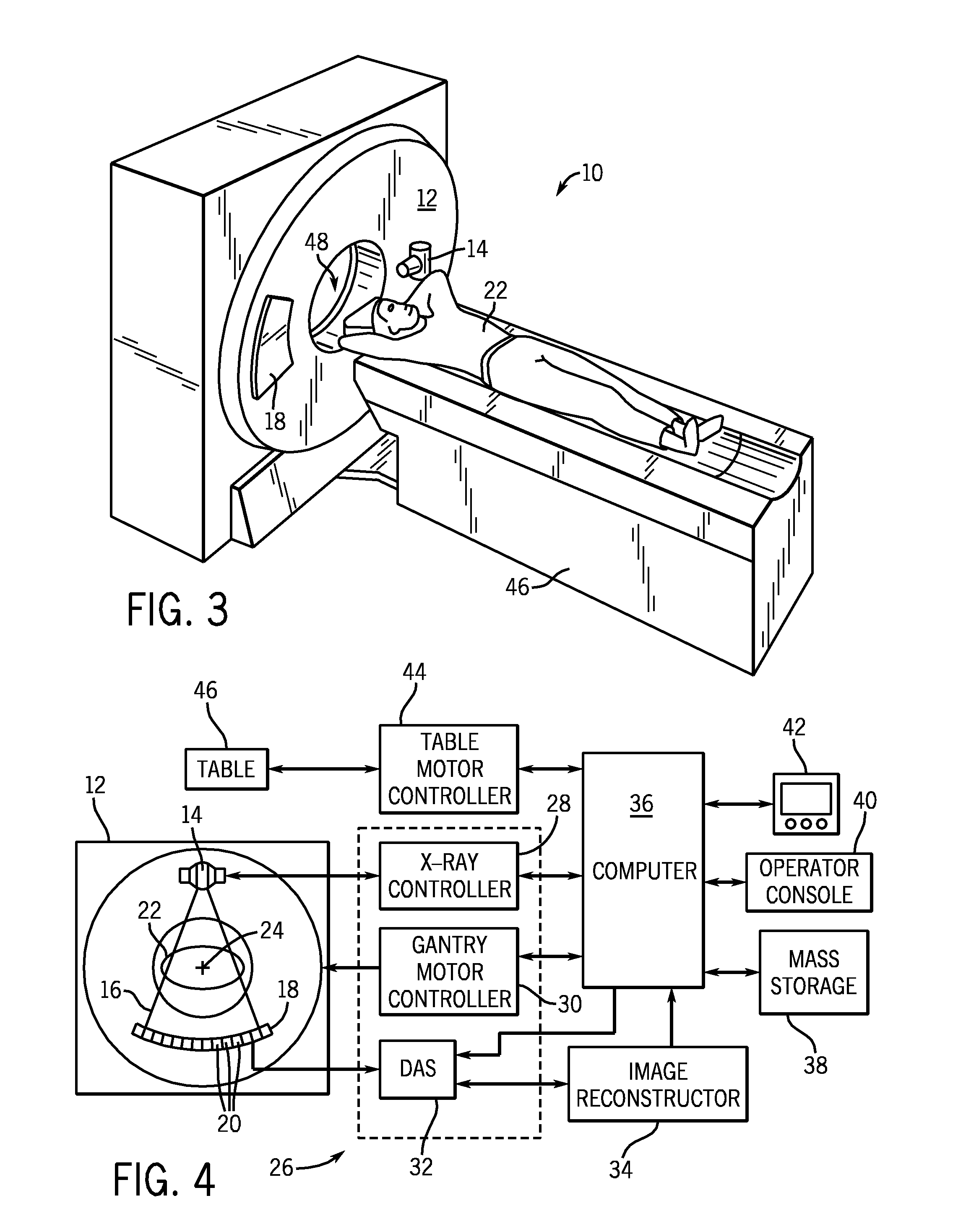
[0034]Referring to FIGS. 3 and 4, an exemplary computed tomography (CT) imaging system 10 is shown as including a gantry 12 representative of a “third generation” CT scanner. One skilled in the art will appreciate that the present invention is applicable with other configured CT scanners, such as those generally referred to as first generation, second generation, fourth generation, fifth generation, sixth generation, etc. scanners. Further, the present invention will be described to a CT detector cell geometry that is applicable with energy integrating cells as well as photon counting and / or energy discriminating cells.

[0035]Gantry 12 has an x-ray source 14 that projects a beam of x-rays 16 toward a detector array 18 on the opposite side of the gantry 12. Detector array 18 is formed by a plurality of detectors 20 which together sense the projected x-rays that pass through a medical patient 22. Each detector 20 produces an electrical signal that represents the intensity of an impingi...


PUM

PropertyMeasurementUnit
angleaaaaaaaaaa
CTaaaaaaaaaa
perimeteraaaaaaaaaa

Abstract

A CT system is constructed to have diagonally oriented perimeter walls of its detector cells. A CT detector comprised of such detector cells has improved spatial coverage (spatial density) and is better equipped for operation with focal spot deflecting x-ray sources. The number of detector channels is also not increased despite the increase in spatial coverage. Moreover, the detector cells can be constructed without much variance from conventional fabrication techniques.

Description

CROSS-REFERENCE TO RELATED APPLICATION[0001]The present application is a continuation-in-part of U.S. Ser. No. 11 / 379,407, filed on Apr. 20, 2006, the disclosure of which is incorporated herein by reference.BACKGROUND OF THE INVENTION[0002]The present invention relates generally to CT imaging systems and, more particularly, to a CT detector with non-rectangular detector cells and to imaging systems and methodologies employing such detectors.[0003]In conventional multi-row CT detectors, a two dimensional array of detector cells extend in both the x and z directions. Moreover, in conventional detectors, each cell of the array is constructed to have a rectangular-shaped active area. This active area is generally perpendicular to a plane of x-ray source rotation and, in the context of energy integrating scintillators, converts x-rays to light. The light emitted by each scintillator is sensed by a respective photodiode and converted to an electrical signal. The amplitude of the electrica...

Claims


Application Information

Patent Timeline
Patent Type & Authority Applications(United States)
IPC IPC(8): H05G1/60A61B6/00G01N23/00G21K1/12
CPCA61B6/032A61B6/4021G01T1/2985G01T1/2018A61B6/4028G06T11/003
Inventor SHAUGHNESSY, CHARLES HUGHDUNHAM, BRUCE MATTHEWSAINATH, PAAVANA
Owner GENERAL ELECTRIC CO
Why Eureka
Try Eureka