Power transmission belt

a transmission belt and engineered surface technology, applied in the direction of driving belts, belts/chains/gearrings, v-belts, etc., can solve the problems of belt noise, rib surface sloughing, slipping, chatter, etc., and achieve the effect of reducing or eliminating slip nois

Active Publication Date: 2007-10-25
THE GATES CORP
View PDF52 Cites 34 Cited by
  • Summary
  • Abstract
  • Description
  • Claims
  • Application Information

AI Technical Summary

Benefits of technology

[0012] The invention comprises a belt having a region comprising a nonwoven material region on a pulley engaging surface. The nonwoven region is interpenetrated with an elastomeric compound which makes up a subsurface elastomeric layer. A predetermined amount of friction-modifying agent is included in the elastomeric compound of the elastomeric layer during compounding. The elastomeric compound is an integrally molded region of the belt profile. The friction-modifying agent in the elastomeric compound of the pulley-engaging region significantly reduces or eliminates slip noise, even when the nonwoven surface region has worn off.

Problems solved by technology

It is known that the rib flank surfaces of V- and multi-v-rib belts are subject to sliding wear, temperature extremes, normal, tangential and frictional forces that cause belt noise, rib surface sloughing, slipping, and chatter.
This technique is limited with regard to an engineering approach for composite design, and / or controlling friction, noise, and slippage.
It also creates a stiff structure that resists bending, which can contribute to belt rib cracking and shortened belt life.
Thus, the short fibers themselves can shorten the overall flex life of the belt.
This approach is limited by any adverse effects of the modifier on the physical properties of the belt body, and it results in wasteful use of modifier in non-surface regions and in ground-off portions of belt.
Coatings, applied in a thin layer to minimize dimensional impact to the profile, may not have sufficient durability.
This technique is also limited.
The nonwoven region may abrade and wear off, leaving exposed to the pulley a rib material which may have unsuitable friction and noise characteristics and reduced longevity.
If the rib material must be designed for improved longevity, friction, and noise, for example by adding a friction reducing agent and / or fiber throughout, then the designer has not gained anything in design flexibility by having a separate nonwoven region.

Method used


Image

  • Power transmission belt
  • Power transmission belt
  • Power transmission belt

Examples


examples

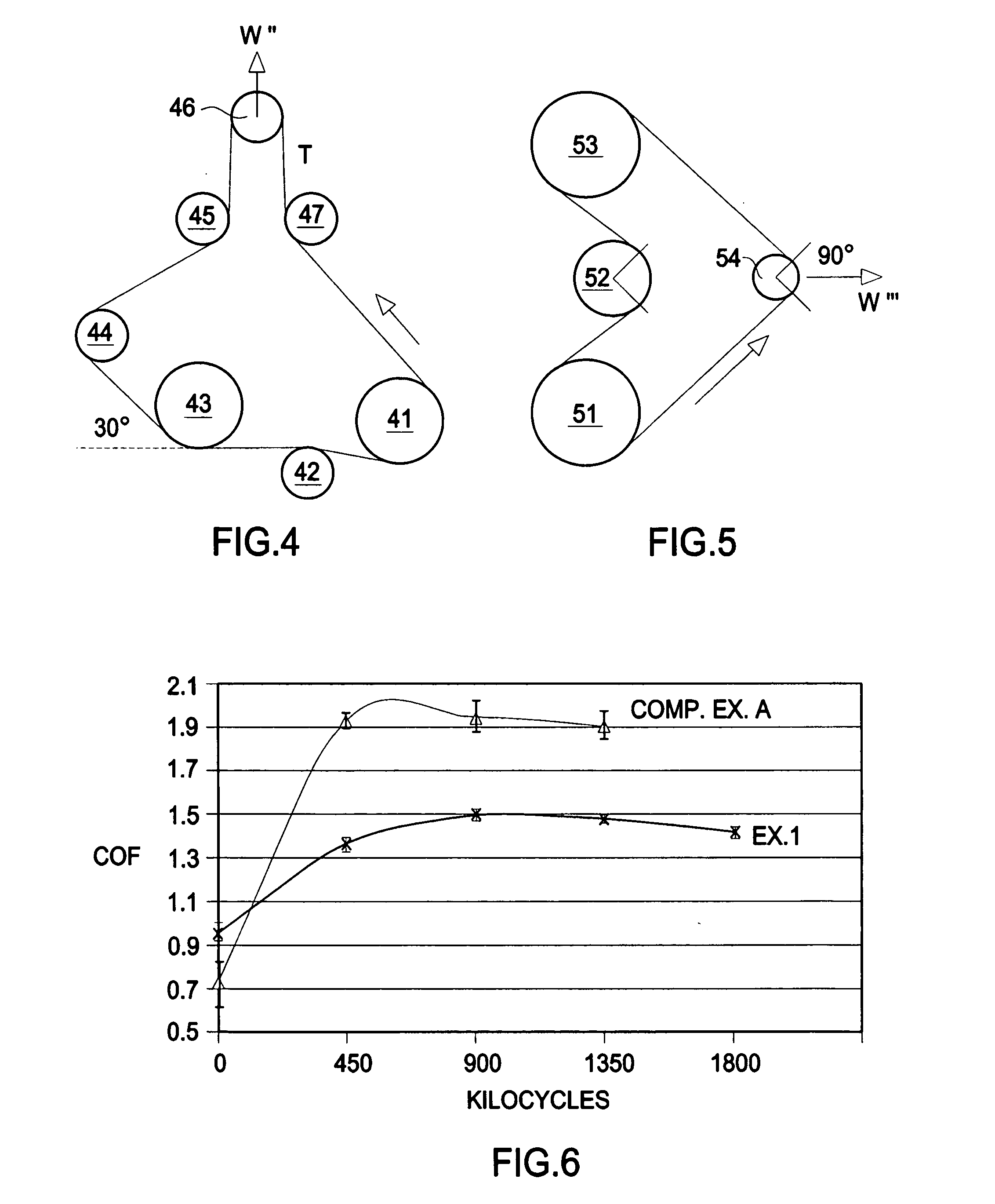
[0045] Noise, friction and durability tests were conducted on an exemplary belt constructed using the formulae noted previously in Table 1. The inventive belt was compared with prior art belts without a subsurface friction-modified region interpenetrating a nonwoven pulley contact surface. The results indicate that misalignment noise generated by the inventive belt is significantly reduced. The inventive belt is also quieter and exhibits a more stable frictional behavior over time.

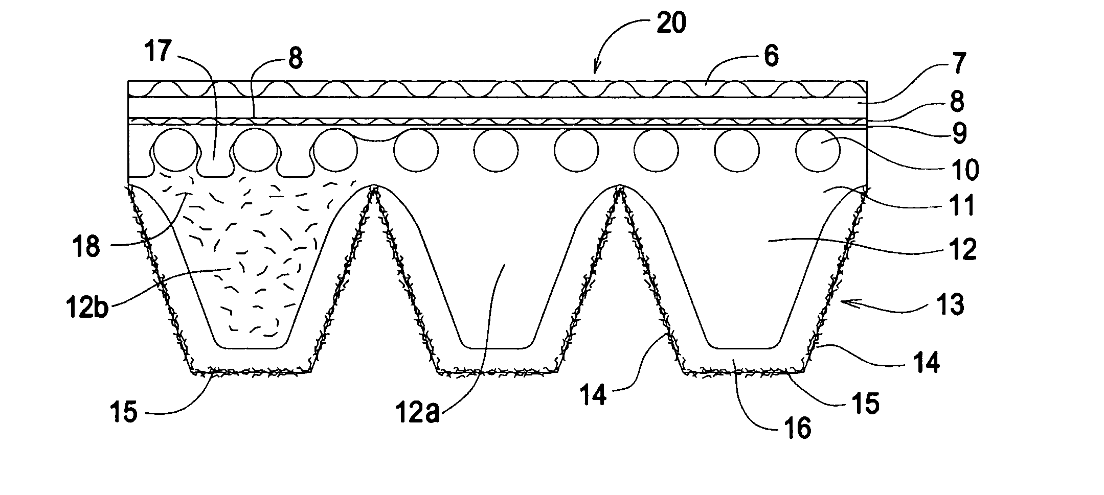
[0046] The test belts comprised an overcord 7, cross-cord 8, gum layer 9, tensile cords 10, a compression section or body 11, a subsurface region 16, and a nonwoven region 15 as described in FIG. 1. The test belts were all EPM-based with polyester tensile cords, nylon cross cord, and two layers of nonwoven of 50% softwood and 50% hardwood. The nonwoven had a basis weight of 4.6 g / m2; porosity of 100 CFM per ft2 per ½″ H2O pressure drop; tensile strength in the machine direction 550 g / inch; tensile strengt...

example 1

[0048] The belt Ex. 1 comprised 10.75 PHR (3 volume %) of Zonyl MP1100 powdered PTFE friction modifier in the subsurface elastomeric composition.

example 2

[0049] The belt Ex. 2 comprised 18.3 PHR (5 volume %) of Zonyl MP1100 friction modifier in the subsurface elastomeric composition.


PUM


Abstract

A power transmission belt comprising a body comprising a first elastomeric material and having tensile members running in a longitudinal direction, the body having a pulley engaging region having a profile; characterized in that the pulley engaging region comprises a surface region and a subsurface region; the subsurface region comprising a second elastomeric material having a friction modifying agent; and the surface region comprising a nonwoven fabric material co-mingled with the second elastomeric material.

Description

BACKGROUND OF THE INVENTION [0001] The invention relates to power transmission belts having an engineered surface and more particularly, to power transmission belts having an engineered surface comprising a region having a nonwoven material and a friction reducing agent. [0002] It is known in the art to make power transmission belts from elastomeric materials having an embedded tensile member. The belts may describe a multi-rib, toothed, v-belt, or flat profile. The belts run in pulleys having a matching profile. [0003] It is known that the rib flank surfaces of V- and multi-v-rib belts are subject to sliding wear, temperature extremes, normal, tangential and frictional forces that cause belt noise, rib surface sloughing, slipping, and chatter. It is also known that power transmission capacity and belt longevity are functions of several factors, including the type of material contacting the pulley surfaces. These issues are conventionally addressed by incorporating a high loading of...

Claims


Application Information

Patent Timeline
Patent Type & Authority Applications(United States)
IPC IPC(8): F16G1/00F16G5/00
CPCF16G5/20F16G1/28
Inventor SOUTH, BOBBIE E.
Owner THE GATES CORP
Why Eureka
Try Eureka