Variable stiffness catheter assembly

a catheter and variable technology, applied in the field of intravascular catheters, can solve the problem that the physician is typically not able to manipulate the distal portion of the catheter directly, and achieve the effect of increasing the pushability of the catheter, variable stiffness, and increasing the stiffness

Inactive Publication Date: 2007-10-25
BOSTON SCI SCIMED INC
View PDF34 Cites 179 Cited by
  • Summary
  • Abstract
  • Description
  • Claims
  • Application Information

AI Technical Summary

Benefits of technology

[0011] In one aspect, the present invention relates to a catheter that has variable stiffness due to the strategic placement of at least one section of EAP at different locations on the catheter. Actuation of the at least one section of EAP causes the region surrounding the EAP section to increase in stiffness, thereby increasing the pushability of the catheter. Alternatively, actuation of the at least one section of EAP causes the region surrounding the EAP section to decrease in stiffness, thereby increasing flexibility of the catheter. In one embodiment, the at least one section of EAP forms part of either the inner or outer shaft. In one embodiment, the at least one section of EAP is a longitudinal strip. In one embodiment, the catheter shaft is manufactured of EAP. In one embodiment, the at least one section of EAP forms the outer surface of the inner shaft. In one embodiment, the at least one section of EAP is located in the catheter tip. In one embodiment, a braid is used as the electrode for the at least one EAP section in the variable stiffness catheter. In one embodiment, the EAP allows for better wire movement and flexibility. In at least one embodiment, at least one section of EAP volumetrically contracts when actuated so that the balloon remains taut when other portions of the catheter are manipulated to improve the catheter's pushability.
[0012] In one aspect, the invention relates to a catheter that has an improved capability to navigate the vasculature system due to strategic positioning of at least one section of EAP at different locations on the catheter. In one embodiment, at least one section of EAP is positioned on the inner shaft. In one embodiment, at least one section of EAP is located only on one side of the inner shaft to control the deflection of the distal tip. In one embodiment, at least one section of EAP changes the spatial configuration of the catheter to improve steering around corners. In one embodiment, the guidewire has at least one section of EAP. In one embodiment, the guide catheter has at least one section of EAP. In one embodiment, the catheter tip has at least one section of EAP. In one embodiment, the at least one section of EAP in an actuated state causes the PT guidewire to contract axially.

Problems solved by technology

During a percutaneous procedure, the physician typically is not able to manipulate the distal portion of the catheter directly.

Method used


Image

  • Variable stiffness catheter assembly
  • Variable stiffness catheter assembly
  • Variable stiffness catheter assembly

Examples


Embodiment Construction

[0070] While this invention may be embodied in many different forms, there are described in detail herein specific embodiments of the invention. This description is an exemplification of the principles of the invention and is not intended to limit the invention to the particular embodiments illustrated.

[0071] For the purposes of this disclosure, like reference numerals in the figures shall refer to like features unless otherwise indicated.

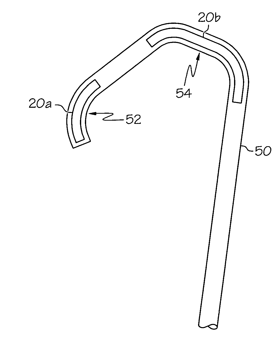
[0072]FIGS. 1a-c depict different ways EAP 20 can behave when actuated. All changes in the geometry of EAP 20, e.g. changing its linear length, are a result of the configuration of the EAP and the substrate it is put on. FIG. 1a depicts how EAP 20 can increase or decrease its linear length. When EAP 20a is actuated, the linear length increases, the additional length denoted by portion 20b. The EAP 20 may also be configured so that it decreases in length upon actuation. FIG. 1b shows how EAP 20 can bend when actuated with 20a denoting the EAP 20 p...


PUM

PropertyMeasurementUnit
flexibilityaaaaaaaaaa
electric electroactiveaaaaaaaaaa
ionic electroactiveaaaaaaaaaa

Abstract

A catheter comprising an outer shaft comprising a first section of electroactive polymer. The first section of electroactive polymer affecting either the flexibility of the catheter or the steerability of the catheter.

Description

CROSS-REFERENCE TO RELATED APPLICATIONS [0001] Not Applicable STATEMENT REGARDING FEDERALLY SPONSORED RESEARCH [0002] Not Applicable FIELD OF THE INVENTION [0003] The present invention relates generally to intravascular catheters for performing medical procedures. BACKGROUND OF THE INVENTION [0004] Intravascular catheters are currently utilized in a wide variety of minimally-invasive or percutaneous medical procedures. Generally, an intravascular catheter enables a physician to remotely perform a medical procedure by inserting the catheter into the vascular system of the patient at an easily accessible location and navigating the tip of the catheter to a desirable target site. By this method, virtually any target site in the patient's vascular system may be remotely accessed. [0005] Typically, a percutaneous procedure begins with the step of inserting a distal portion of the catheter into the patient's vasculature at a convenient location. Once the distal portion of the catheter has...

Claims


Application Information

Patent Timeline
Patent Type & Authority Applications(United States)
IPC IPC(8): A61M31/00A61M25/00A61F2/958
CPCA61M25/0009Y10T29/49826A61M25/0053A61M25/0054A61M25/0138A61M25/0158A61M25/09A61M25/1006A61M2025/0024A61M2025/0035A61M2025/0039A61M2025/0058A61M2025/0063A61M2025/0915A61M2025/09175A61M25/0045
Inventor VOLK, ANGELA KORNKVENEIDENSCHINK, TRACEESUTERMEISTER, DEREKWISE, DEREKGUNDERSON, RICHARD C.WEBER, JANBLIX, JOHNOLSON, RICHARDJAGGER, KARL A.
Owner BOSTON SCI SCIMED INC
Why Eureka
Try Eureka