Method and system of modeling leakage

a leakage and modeling technology, applied in the field of methods and systems of modeling leakage, can solve the problems of exponential dependency between vt and leakage, leakage across devices, spice techniques may not be the most appropriate technique for modeling leakage,

Inactive Publication Date: 2007-10-25
GLOBALFOUNDRIES INC
View PDF19 Cites 15 Cited by
  • Summary
  • Abstract
  • Description
  • Claims
  • Application Information

AI Technical Summary

Benefits of technology

[0008] In a first aspect of the invention, a method of modeling power leakage for a design comprises providing one or more cell libraries comprising parameters of cell characteristics and providing a module configured to determine cell leakages of a cell for a process, voltage and temperature (PVT) corner using the cell characteristics contained in the one or more cell libraries, in combination with one or more components that determine the acceleration of leakage due to PVT, using an amount of devices in a leakage path (Fckt) and a leakage distribution (Fchip). In this aspect of the invention, the need to recharacterize the one or more cell libraries is eliminated when parameters in the one or more components are updated.
[0012] The results provided by the module in combination with cell contents from the one or more cell libraries are interfaced with an electronic design automation tool to determine cell leakages while eliminating a need to recharacterize the one or more cell libraries when parameters in the one or more components are updated.

Problems solved by technology

Leakage across a device is one of today's most important VLSI design issues.
(It is well known that there is an exponential dependency between Vt and leakage, e.g., HVt devices leak less but are slower, while LVt transistors are faster but leak far more).
Library characterization using SPICE is, in principle, capable of modeling such leakage; however, SPICE techniques may not be the most appropriate technique for modeling leakage since SPICE models used for library characterization may not reflect effects important for leakage.
Moreover, SPICE characterization is not possible for certain categories of library IP.
Also, it is difficult to update the SPICE models as the process matures and leakage changes in that full re-characterization of the entire cell library would be needed to address even small process shifts, e.g., Vt (voltage threshold), Tox (oxide thickness), recentering and corner re-definition, to name but a few.

Method used


Image

  • Method and system of modeling leakage
  • Method and system of modeling leakage
  • Method and system of modeling leakage

Examples


Embodiment Construction

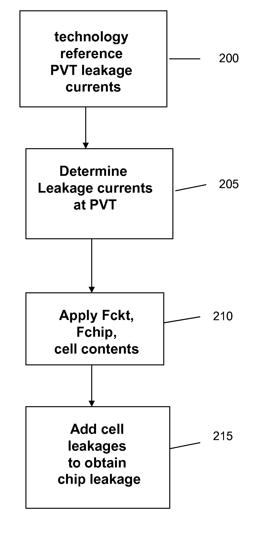
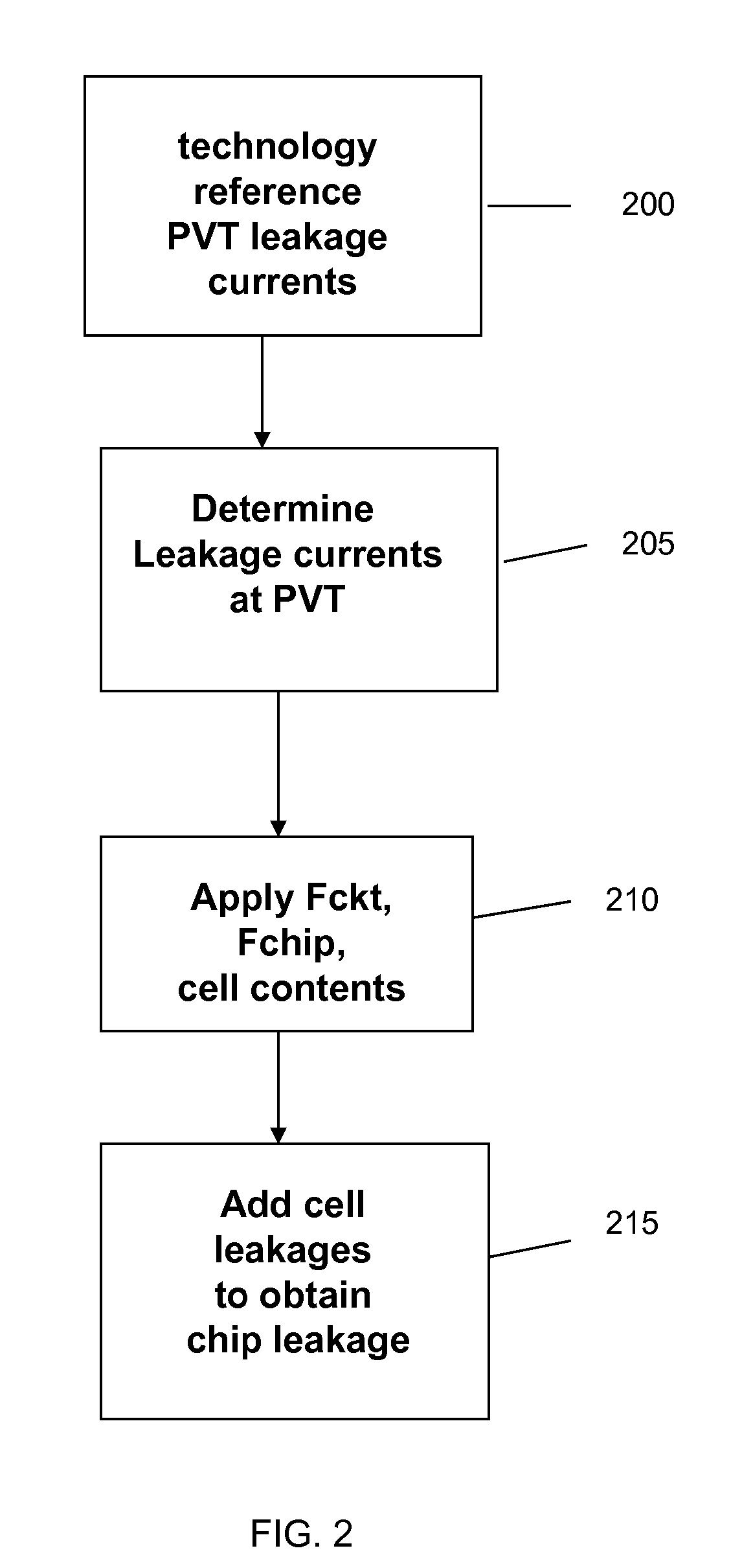
[0020] The invention relates to a method and system of modeling leakage across process, voltage and temperature ranges, taking into account cross-chip variations in process parameters, that allows the total chip leakage power to be estimated prior to manufacturing the chip. More particularly, the invention uses a versatile method to predict leakage in silicon across a wide process, voltage and temperature range, and across library variations such as low Vt gates applied to a method of production of cell power models.

[0021] In implementation, equations implemented in accordance with the method and system of the invention predict the leakage in CMOS logic, in which the equations use device characteristics and technology parameters to model leakage of a cell as part of a complete chip. The cell models built in the manner according to the method and system of the invention are easy to update for process shifts and can be used for both the typical voltage and temperature ranges for desi...


PUM


Abstract

A method and system of modeling power leakage for a design comprises providing one or more cell libraries comprising parameters for particular device characteristics and providing a module configured to determine of cell leakages of a device for a PVT corner. In determining the cell leakage, the module uses the device characteristics contained in the one or more cell libraries, in combination with one or more components at a PVT for a predetermined application and an amount of devices in a leakage path (Fckt) and a leakage distribution (Fchip). There is no need to recharacterize the one or more cell libraries.

Description

FIELD OF THE INVENTION [0001] The invention relates generally to a method and system of modeling leakage across a device and more particularly to a method and system of accurately modeling leakage across process, voltage and temperature ranges, taking into account cross-chip variations in process parameters, that allows the total chip leakage power to be estimated prior to manufacturing the chip. BACKGROUND OF THE INVENTION [0002] Leakage across a device is one of today's most important VLSI design issues. Leakage is the uncontrolled (“parasitic”) current flowing across region(s) of semiconductor structure / device in which no current should be flowing; e.g., current flowing across the gate oxide in MOS. [0003] In any event, accurate and consistent leakage power estimation is critical at all stages of ASIC design. For example, cell level leakage models are needed to drive optimization tools which would allow the ASIC designer to budget real chip leakage used for power optimization in ...

Claims


Application Information

Patent Timeline
Patent Type & Authority Applications(United States)
IPC IPC(8): G06F17/50H03K19/00
CPCG06F17/5036G06F30/367
Inventor ENGEL, JAMESJLICHTENSTEIGER, SUSAN K.SULVA, PAUL J.WISSEL, LARRY
Owner GLOBALFOUNDRIES INC
Why Eureka
Try Eureka