Ground Drilling Hammer and the Driving Method

a technology of ground drilling hammer and driving method, which is applied in the direction of manufacturing tools, percussive tools, portable drilling machines, etc., can solve the problems of affecting the operation of the hammer, so as to prevent the degradation of a function

Inactive Publication Date: 2007-11-01
EVERDIGM ROCK TOOLS CORP
View PDF60 Cites 19 Cited by
  • Summary
  • Abstract
  • Description
  • Claims
  • Application Information

AI Technical Summary

Benefits of technology

[0005] Accordingly, the present invention has been made to solve the above-described problems, and it is an object of the present invention to provide a pneumatic operated hammer for use in earth and rock drilling and boring operations and driving method thereof, in which the upward and downward movement of a piston using compressed air is efficiently carried out a new design of the supply scheme of compressed air, in which the piston is fabricated to have a predetermined length fitting for a desired drilling work so that it is possible to prevent a degradation in a function or a damage of the hammer due to water back-flowing into the drilling hammer, in which the flow structure of compressed air is efficiently improved through an additional formation of variable compressed-air chambers so that the ascending and descending of the piston is performed smoothly to thereby enhance the drilling work efficiency, and in which the environment of the drilling work is greatly improved in terms of time and economic aspect. Technical Solution
[0007] According to the present invention to which this operation principle is applied, the compressed-air chambers are formed between the piston and the casing to enable the piston to be reciprocatingly moved upwardly and downwardly within the casing to which compressed air is fed, and the rapid upward and downward movement of the piston is effected by the compressed air fed through air passageways communicating with the compressed-air chambers to thereby further enhance its striking force.

Problems solved by technology

However, the above patent has demerits in that a known piston of the down-on-the hole hammer is geometrically very complex, its repair and maintenance is very difficult and a mechanical trouble occurs frequently to thereby degrade a working efficiency.
Further, when the lower end of the piston strikes an anvil portion of a drill bit, a compressed air supply is interrupted to thereby hinder the operation of the hammer.
However, this patent also embraces shortcomings in that the supply of pressurized air is performed only through an aperture of a central passageway of a piston and outlet apertures of a feed tube, so that the function of the compressed air for the ascending and descending, i.e., the upward and downward movements of a piston is not carried out efficiently, and since the arithmetic ratio of resistance and density of the component parts is applied to the drilling hammer, the drilling hammer does not have a function capable of preventing back flow of underground water or sludge at the time of the actual drilling work.
Furthermore, since a check valve for selectively blocking pressurized air is readily worn or exceeds fatigue strength due to a frequent striking to thereby suffer a partial crack or damage, leading to the frequent stopping of the drilling work.
As a result, the work efficiency is deteriorated and the drilling equipment is not easy to repair and maintain.

Method used


Image

  • Ground Drilling Hammer and the Driving Method
  • Ground Drilling Hammer and the Driving Method
  • Ground Drilling Hammer and the Driving Method

Examples


first embodiment

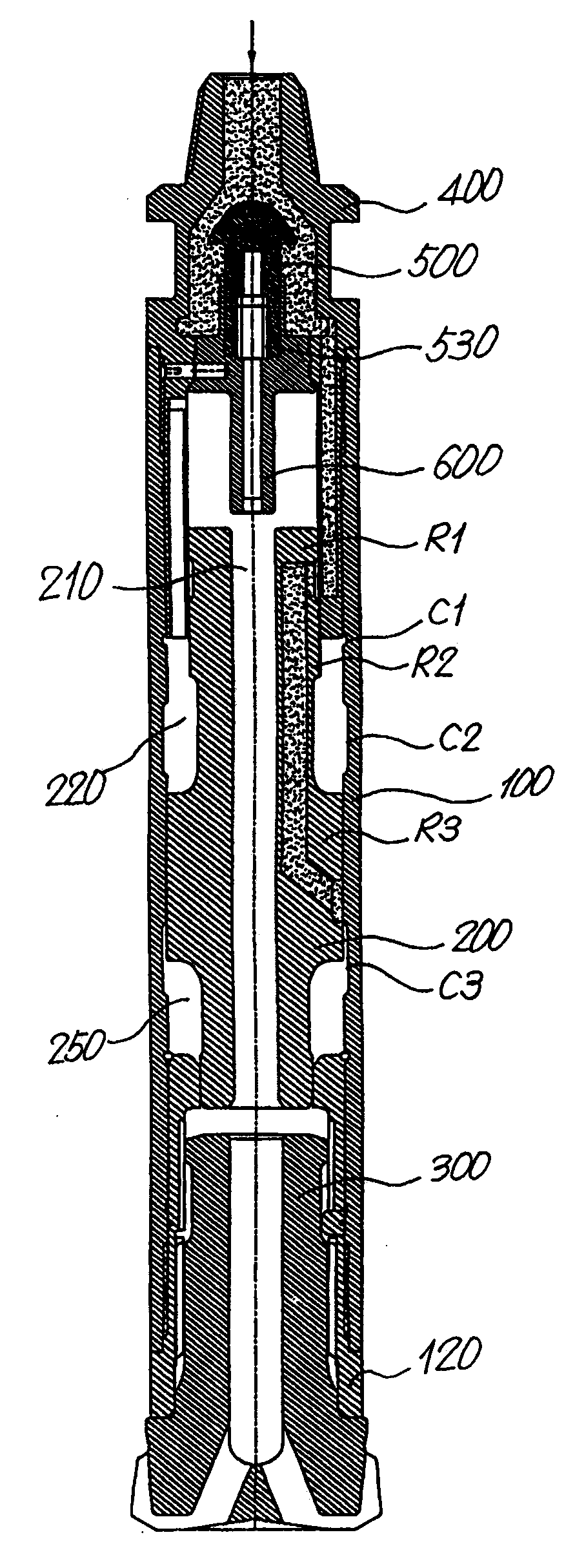
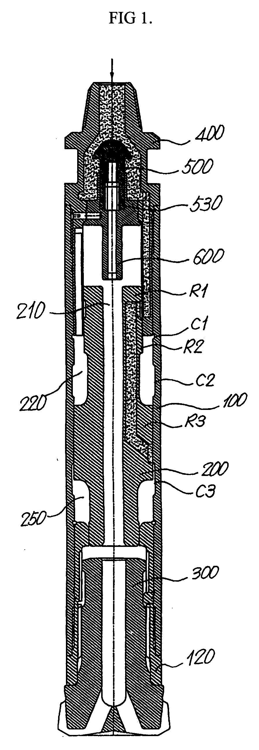
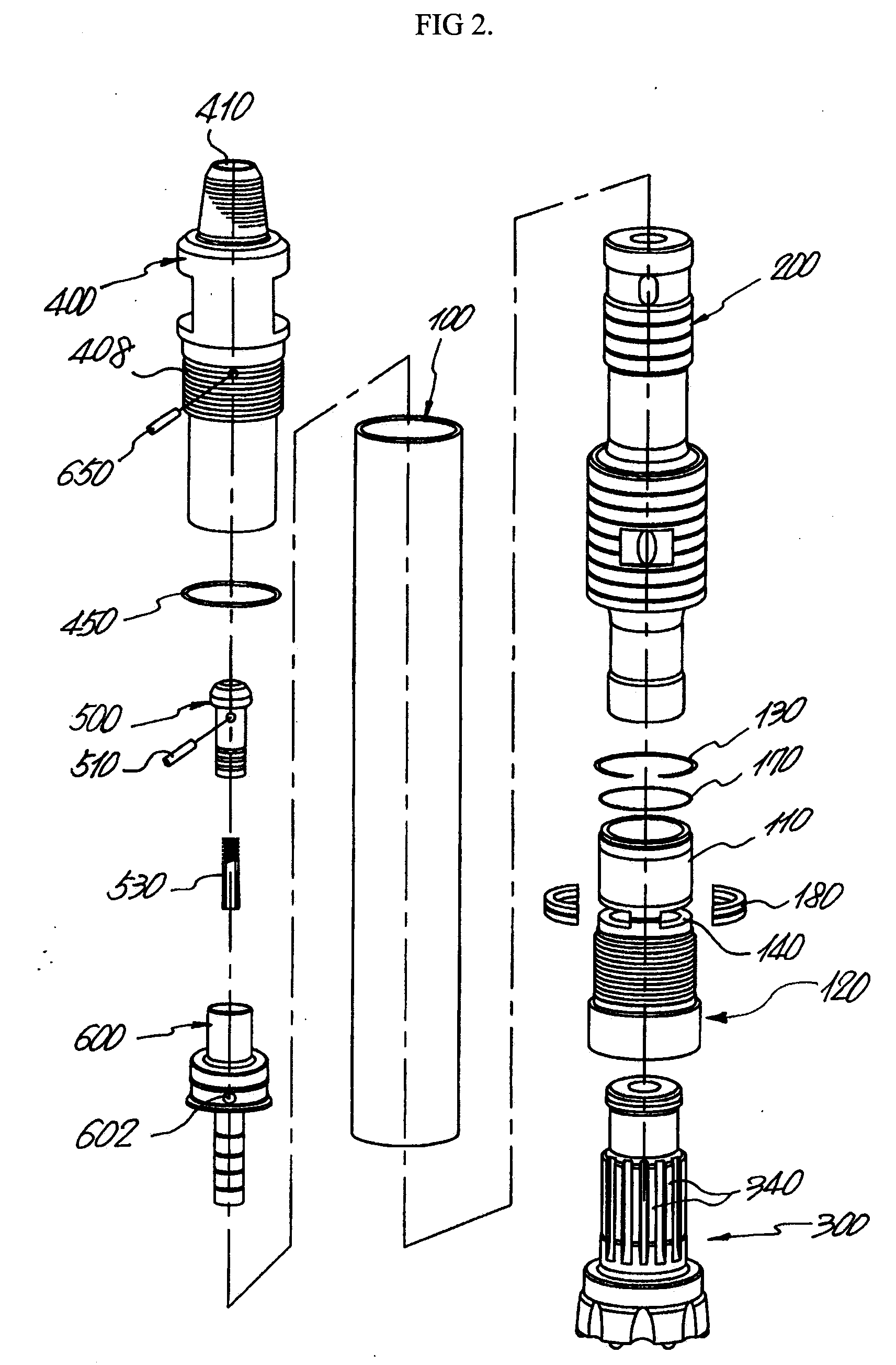
[0031] As shown in FIG. 1, the present invention is implemented with a concrete shape and structure of the following components. That is, in case of a pneumatic operated hammer for rock drilling in which a piston 200 strikes a button bit 300 while vertically reciprocating in a cylindrical casing 100 so that the drilling work is carried out, a back head 400 is screw-engaged with the upper portion of the casing 100 with the back head having a center hole 410 for supply of compressed air and an inner hollow space 420 for receiving a check valve 500 therein. A guide 600 is engaged with the lower end of the check valve 500 by means of a coil spring 530 and is construed such that its shaft portion 610 advances to and retracts from an inner hole 210 of the piston 200. A chuck 120 formed integrally with a bushing portion 110 is disposed at an inner periphery of the lower end portion of the casing 100 so that the piston 200 and the button bit 300 are prevented from being shaken due to an axi...

second embodiment

[0064] As shown in FIG. 9, in a pneumatic operated hammer for rock drilling in an assembly state according to the present invention, first, the back head 40 and the casing 10 are engaged with by means of a joint 70. The reason for this is that the joint 70 is formed with a guide seating portion 71 and a compressed air groove 72 so that the guide 60 is seated from the top to the bottom of the joint 70 in the drawing to prevent the generation of a clearance due to vibration during the drilling work.

[0065] Also, a striking guide groove extending from the center hole is formed between the inner hole 21 constituting the inner diameter of a piston 20 and the outer periphery of the piston. The piston has a first chamber partition wall 28 and a second chamber partition wall 28′ positioned below the first chamber partition wall 28 protrudingly formed at the outer periphery thereof, and a sealing support ring mounting groove 29 formed just below the first chamber partition wall 28 for mountin...

third embodiment

[0089] The drilling hammer according to the present invention, as shown in FIG. 16 to FIG. 21, includes a back head 40a to which compressed air is supplied from the outside, a joint 70a for engaging the back head 40a with a casing 10a, a check valve 50a installed inside the joint 70a for selectively interrupting the supply of the compressed air, a cylindrical guide 60a for supporting the check valve 50a, a piston 20a adapted to ascend and descend within the casing 10a and the guide 60a and having a plurality of compressed air passageways formed therein, and a button bit 30a mounted in such a fashion as to ascend and descend in the casing 10a for performing the drilling work through a descending striking force of the piston 20a and a rotational force of the casing 10a.

[0090]FIG. 17 is an exploded perspective view of a pneumatic operated hammer for rock drilling according to a third embodiment of the present invention.

[0091] In FIG. 17, the back head 40a and the casing 10a are screw...


PUM

PropertyMeasurementUnit
outer diameteraaaaaaaaaa
outer diameters R1aaaaaaaaaa
lengthaaaaaaaaaa

Abstract

Disclosed herein is a pneumatic operated hammer for rock drilling, the hammer comprising a cylindrical casing, a back head mounted at an upper portion of the casing, a check valve for opening / closing a compressed air passageway in the casing, a guide for supporting the check valve, a piston adapted to ascend and descend with compressed air in the casing, and a button bit for performing a drilling work through the striking of the piston. The piston is extended to a certain length to conform to the work condition of the pneumatic hammer to thereby prevent a water back-flow phenomenon in which underground water, etc., is introduced into the drilling equipment during the drilling work, compressed air passageways and variable compressed air chambers are formed between the piston and the casing so that when the piston ascends by the compressed air, it abruptly ascends at a load-free state, and the piston has axial portions with a reference diameter and different outer diameters so that it is possible to manufacture a hammer bit having a plurality of variable compressed air chambers formed between the casing the piston to fit for the work capacity. The piston ascended in a load-free state strikes the button bit with its rapid and strong striking force produced by the compressed air supplied from the variable chambers while abruptly descending to thereby perform the drilling work.

Description

TECHNICAL FIELD [0001] The present invention relates to a pneumatic operated hammer for use in earth and rock drilling and boring operations and driving method thereof, and more particularly, to such a drilling pneumatic hammer in which air passageways are arranged concentrically at regular intervals about a central axis of the back head to supply the compressed air required for driving the hammer in a central and distributed manner, in which the piston is extended to a certain length to conform to the work condition of the pneumatic hammer to thereby prevent a water back-flow phenomenon in which underground water, etc., is introduced into the drilling equipment during the drilling work, in which the outer diameters of respective axial portions of the piston are formed differently from one another to form variable compressed air chambers between the piston and the casing so that when the piston ascends by the compressed air, it abruptly ascends at a load-free state, and in which the...

Claims


Application Information

Patent Timeline
Patent Type & Authority Applications(United States)
IPC IPC(8): B25D9/00
CPCE21B4/14
Inventor LIM, BYUNG-DUK
Owner EVERDIGM ROCK TOOLS CORP
Why Eureka
Try Eureka