Container with venting closure assembly

a technology of venting and closure assembly, which is applied in the field of containers, can solve the problems of dislocation of containers and no longer effective barrier to protect contents from moist air

Inactive Publication Date: 2007-11-01
SILGAN PLASTICS CORP
View PDF42 Cites 23 Cited by
  • Summary
  • Abstract
  • Description
  • Claims
  • Application Information

AI Technical Summary

Problems solved by technology

As is well known, certain products such as coffee tend to outgas and this can cause distortion of the container if the pressure in the container becomes too great, especially in thin walled containers.
Although it is desirable to vent the escaping gas, some gas retention is desirable to provide a positive pressure to preclude entry of the ambient air into the container since moisture and gases may be deleterious to the product.
This foil seal is removed by the user in order to gain access to the product therein after which there is no longer an effective barrier to protect the contents from moist air, etc.

Method used


Image

  • Container with venting closure assembly
  • Container with venting closure assembly
  • Container with venting closure assembly

Examples


Embodiment Construction

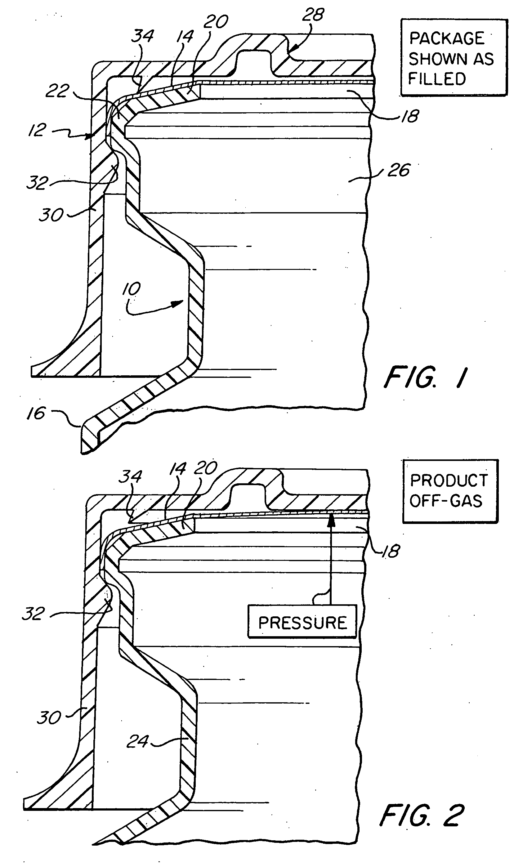
[0017] Turning first to FIG. 1 of the attached drawings, therein illustrated is a fragmentary container assembly embodying the present invention and comprised of a container generally designated by the numeral 10, a cap generally designated by the numeral 12, and a removable foil seal generally designated by the numeral 14.

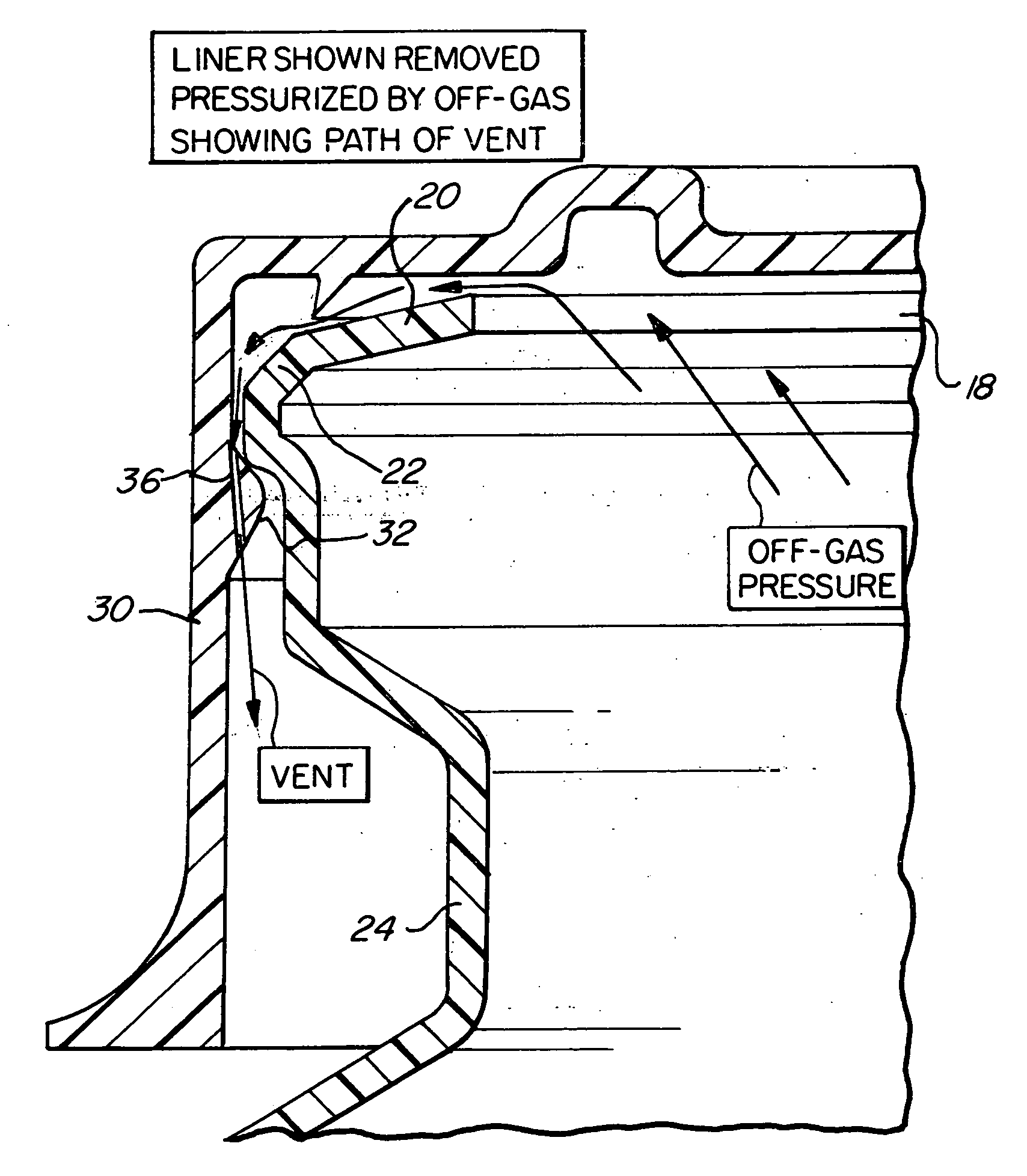
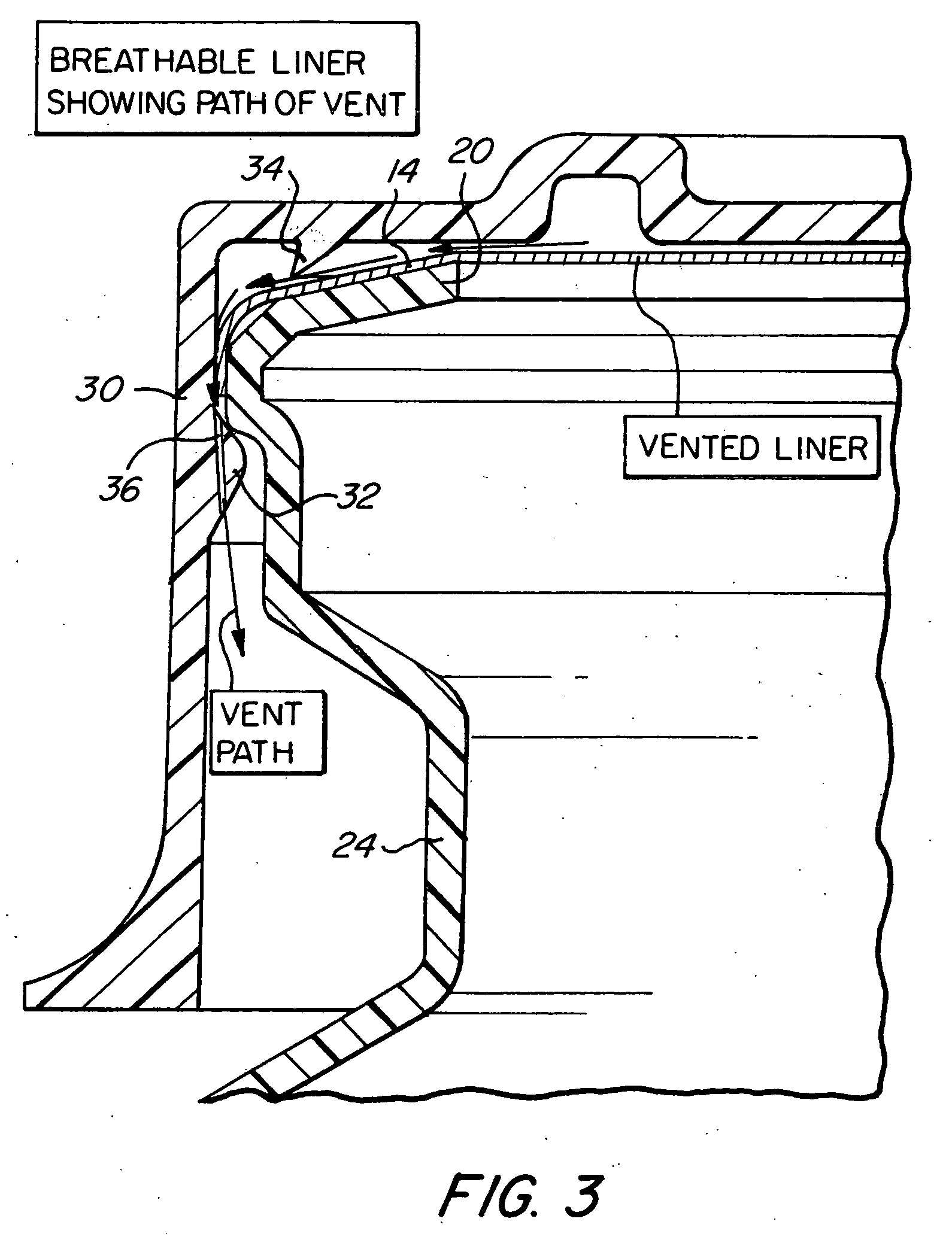
[0018] The container 10 has a sidewall 16, a bottom wall (not shown) and a mouth 18 at its upper end bounded by an inturned lip portion 20. Adjacent its upper end, the sidewall 16 has an outwardly oriented shoulder 22 which extends about the circumference thereof and a reduced diameter neck portion 24 therebelow. The foil seal 14 extends over the mouth 18 and is adhered to the lip portion 20, thus sealing the interior chamber 26.

[0019] The cap 12 has a top wall generally designated by the numeral 28 and a depending skirt generally designated by the numeral 30, and a snap bead 32 is formed on the inner surface. When the cap 12 is pushed onto the container 10, the...


PUM


Abstract

A container for a product which off-gases has a container body with a base wall, sidewall and a large mouth at its upper end bounded by a lip and having an outwardly extending shoulder adjacent the upper end of the sidewall, and a foil seal which extends over the mouth and is adhered to the lip. The foil seal having a valve therein permitting gases in the container body to exit therethrough. A cap having a top wall and a depending skirt with an internal peripheral snap bead abuts the shoulder on the sidewall of the container body. The top wall of the cap has a depending flexible ring seal bearing on the lip and the inside surface of the cap has channels extending downwardly along the inside surface of the skirt. Gas pressure in the container body will cause the valve in the foil seal to release gas from the interior of the container body into the space in the cap and the pressure of the gas in the ring seal is deflected from the lip to allow the gas to flow thereby and outwardly in the channels in the cap.

Description

BACKGROUND OF THE INVENTION [0001] The present invention relates to containers and, more particularly, containers for products which outgas and which employ venting elements. [0002] As is well known, certain products such as coffee tend to outgas and this can cause distortion of the container if the pressure in the container becomes too great, especially in thin walled containers. As a result, some containers use a wall thickness which is increased from that required for a product which does not outgas. This outgassing problem is accentuated with some packaging techniques which utilize the step of purging the ground and roasted coffee to displace oxygen as described in Canadian Patent No. 1,309,992. [0003] Various structures have been proposed to vent the gas evolved from the product such as those shown in Thomas et al Patent Publication US 2004 / 0096552; Costa et al U.S. Pat. No. 5,370,306; and Jeor U.S. Patent Publication US 2004 / 0173626. [0004] Although it is desirable to vent the...

Claims


Application Information

Patent Timeline
Patent Type & Authority Applications(United States)
IPC IPC(8): B65D51/16B65D53/00B65D41/00
CPCB65D51/1661B65D51/1644
Inventor MENGEU, GARY L.
Owner SILGAN PLASTICS CORP
Why Eureka
Try Eureka