Double-injection molding method

a technology of injection molding and injection molding, which is applied in the direction of ceramic shaping apparatus, other domestic objects, manufacturing tools, etc., can solve the problems of affecting the appearance, difficult to clean contaminants, and dirty edges of consumer electronics casings, etc., to achieve the effect of reducing the quantity of plastic materials, increasing the strength of cell phone casings, and improving the durability

Inactive Publication Date: 2007-11-01
TAIWAN GREEN POINT ENTERPRISE
View PDF1 Cites 20 Cited by
  • Summary
  • Abstract
  • Description
  • Claims
  • Application Information

AI Technical Summary

Benefits of technology

[0018]According to an embodiment of the present invention, a double-injection molding method is applied to manufacturing consumer electronics casings such as a cell phone casing, which comprises a cell phone shell and a cell phone screen. Because designing the tolerance on an injecting mold is not needed, the plastic materials of the cell phone shell and screen are connected tightly with each other. Not only are the durability and the strength of the cell phone casing increased, but also the thickness of the cell phone and the quantity of the plastic materials are decreased. The integrated profile of the entire cell phone casing makes the design of the cell phone casing more flexible to increase the competition of the products.
[0019]In addition, a double-injection molding method in accordance with the present invention does not need other manufacturing or assembling procedures, such as using adhesives to combine the shell and screen of the cell phone, after products are injected. Therefore, the manufacturing procedures can be shortened and the manufacturing speed and the yields can be increased.

Problems solved by technology

However, the notches of consumer electronics casings will be dirty and clogged with contaminants after long-term use.
The contaminants are not easy to be cleaned, and will influence the appearance.
Moreover, the notches produced by the tolerance will decrease the structural strength at the boundary of different plastic materials.
Therefore, the cost of the plastic materials of the products will increase and the profile design of the product will be limited (ex. thickness limitation).
In addition, parting lines or boundary lines will not be produced between the different plastic materials.

Method used


Image

  • Double-injection molding method
  • Double-injection molding method
  • Double-injection molding method

Examples


Embodiment Construction

[0034]Reference will now be made in detail to the present preferred embodiments of the invention, examples of which are illustrated in the accompanying drawings. Wherever possible, the same reference numbers are used in the drawings and the description to refer to the same or like parts.

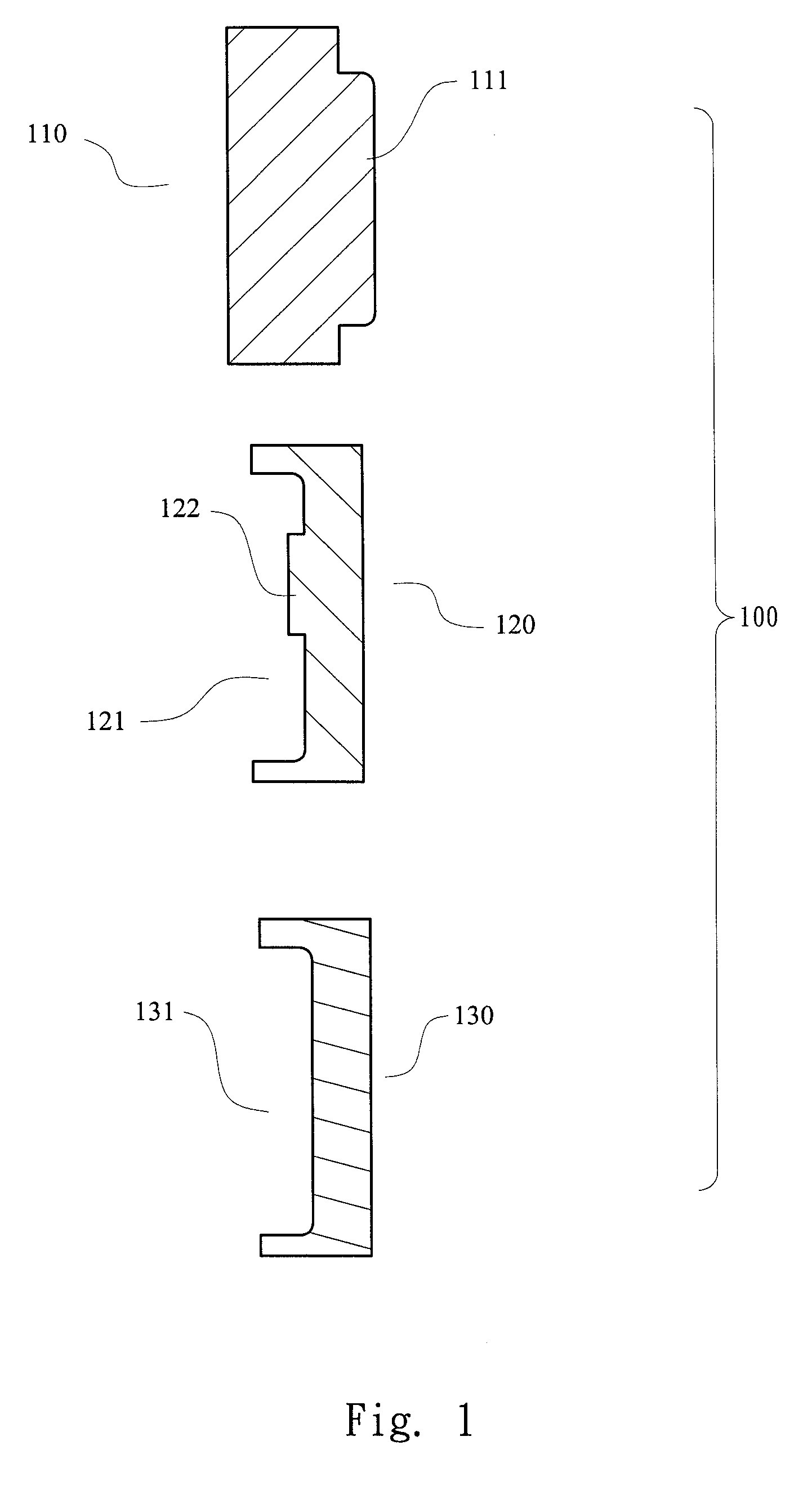
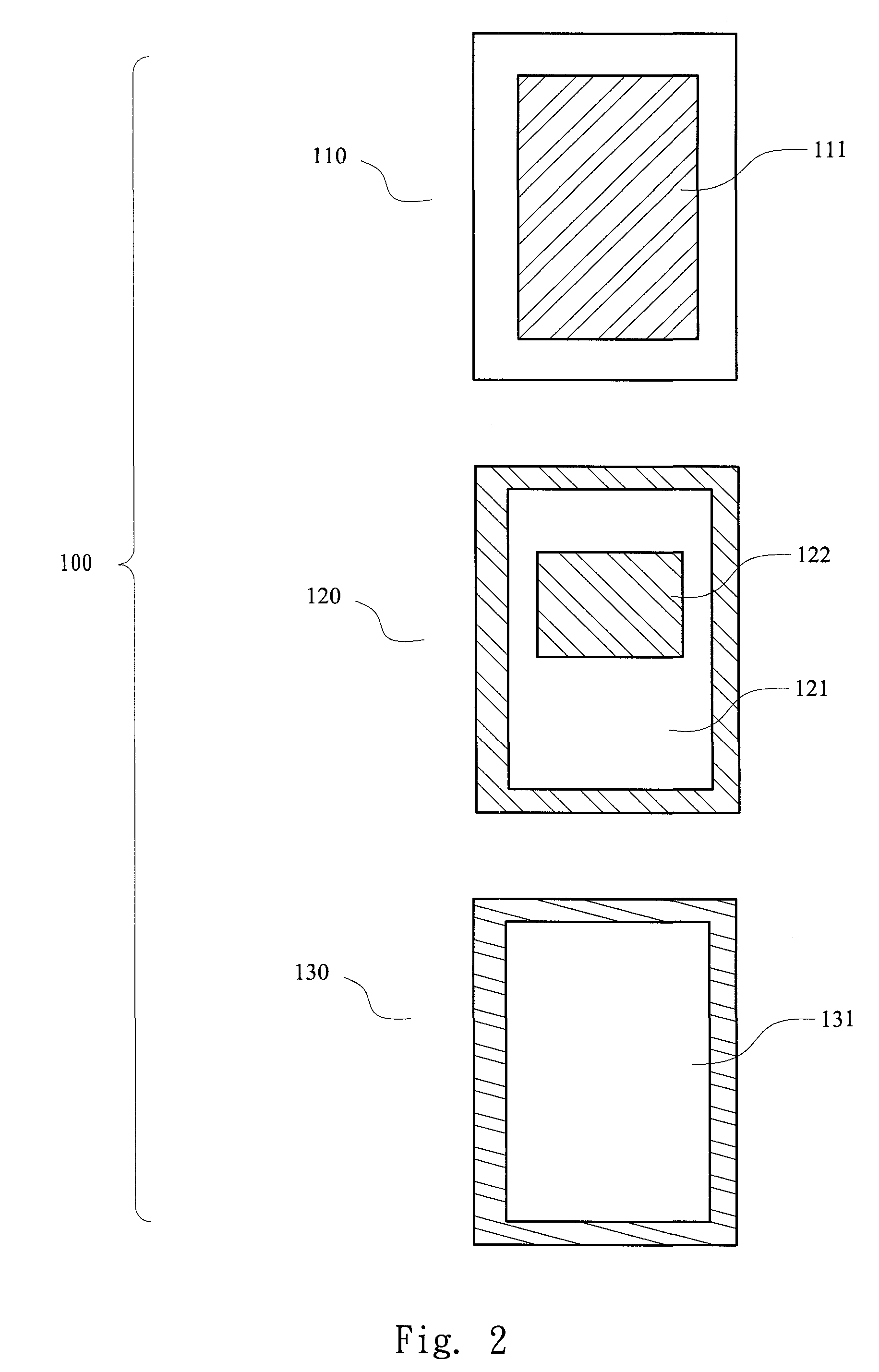
[0035]Refer to FIG. 1 and FIG. 2. FIG. 1 and FIG. 2 illustrate respectively a sectional view and an elevation view of a mold in accordance with the present invention. The mold 100 includes a male mold 110, a first female mold 120 and a second female mold 130. The male mold 110 has one or more than one male core 111 which can combine with the first female mold 120 and the second female mold 130 respectively. For conveniently illustrative purposes only, only one male core 111 is shown in FIG. 1.

[0036]The first female mold 120 has a first cavity 121. The first cavity 121 has one or more than one female core 122. For conveniently illustrative purposes only, only one female core 122 is shown in FIG. 1. Wh...


PUM

PropertyMeasurementUnit
molding efficiencyaaaaaaaaaa
shapeaaaaaaaaaa
structural strengthaaaaaaaaaa

Abstract

Double-injection molding methods through which the products do not have any parting lines between the molding materials comprise a mold, which has at least a male mold and a female mold. The male mold comprises at least one core. The female mold comprises at least one cavity and one core. The core of the male mold and the core of the female mold can be combined tightly. The male mold is stationary but the female mold is removable. The molding method of the present invention is to manufacture a product with two different plastic materials, where these two different plastic materials are injected into the mold in a specific order. And these two different plastic materials connect each other directly. After packing and cooling process, these two different plastic materials are shaped in the mold. A product with a smooth profile at the boundary of two materials is thus performed.

Description

RELATED APPLICATIONS[0001]This application claims priority to Taiwan Application Serial Number 95115495, filed May 1, 2006, which is herein incorporated by reference.BACKGROUND[0002]1. Field of Invention[0003]The present invention relates to a double-injection molding method. More particularly, the present invention relates to a double-injection molding method through which the products do not have any parting lines between the molding materials.[0004]2. Description of Related Art[0005]Plastic moldings such as injection molding, extrusion molding, transfer molding, blow molding, compression molding, etc. are common methods in manufacturing plastic products. Injection molding has high molding efficiency, high yield and easy automation. Injection molding has been applied to manufacturing products with complicated sections, especially for manufacturing consumer electronics casings such as cell phone casings, computer casings, laptop casings, etc. Since the consumer electronics casings ...

Claims


Application Information

Patent Timeline
Patent Type & Authority Applications(United States)
IPC IPC(8): B29C45/16
CPCB29C37/0082B29C45/062B29L2031/3437B29C45/1657B29C45/1615
Inventor KUO, NAN-HUILAI, CHIA-MENGTING, YING-CHIEHLIN, CHI-CHAO
Owner TAIWAN GREEN POINT ENTERPRISE
Why Eureka
Try Eureka