Pump Apparatus and Power Steering

Inactive Publication Date: 2007-11-01
HITACHI LTD
View PDF16 Cites 15 Cited by
  • Summary
  • Abstract
  • Description
  • Claims
  • Application Information

AI Technical Summary

Benefits of technology

[0011]Since a running-in processed portion gradually wears away and is deformed according to actual operation, it is possible to obtain optimal gear shapes in all mesh combinations of gears of the first gear and the second gear and to reduce leakage inside the pump to improve pump performance. This is especially ef

Problems solved by technology

In a gear pump including the internal gear pump, in general, leakage of hydraulic oil from the discharge side to the suction side occurs, which causes reduction of pump efficiency.
Particularly in the internal gear pump, the leakage of the hydraulic oil from the discharge side to the suction side occurs in a gear with a normal form accuracy, particularly when stopping rotation or slowly rotating, at a sliding contact portion of the external gear and the internal gear where a high pressure side and a low pre

Method used


Image

  • Pump Apparatus and Power Steering
  • Pump Apparatus and Power Steering
  • Pump Apparatus and Power Steering

Examples


first embodiment

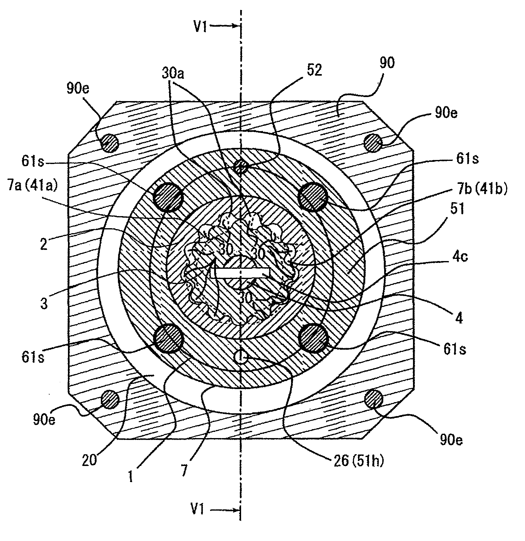
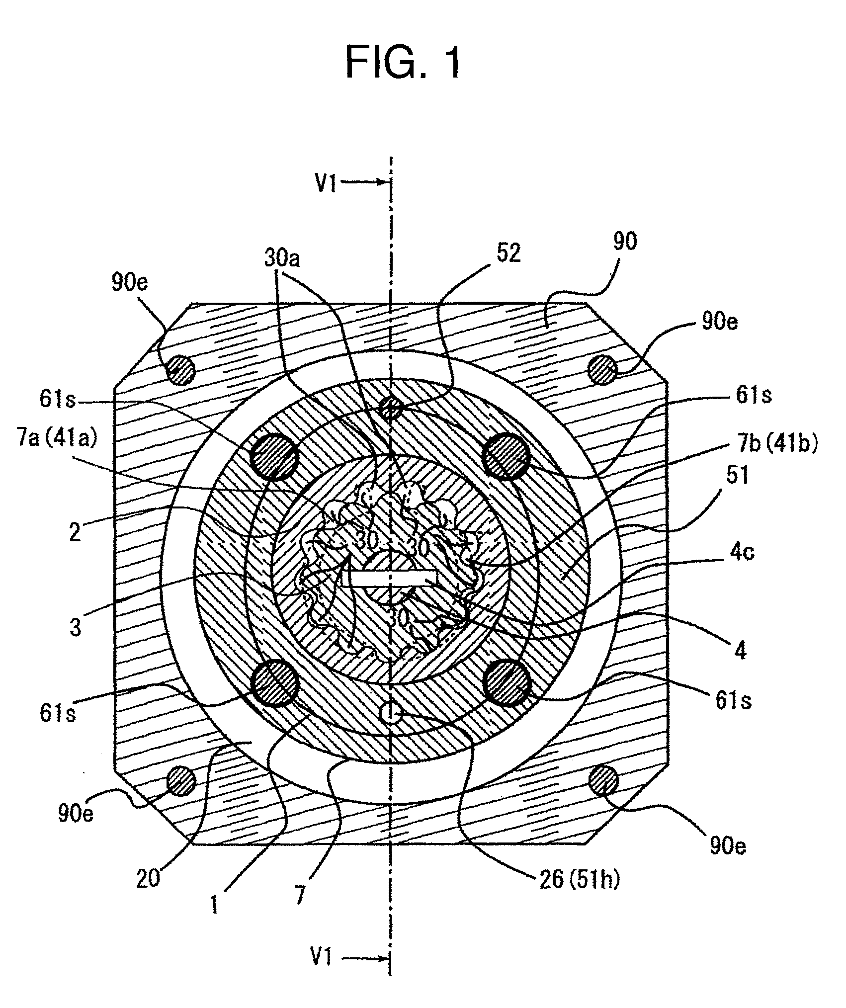
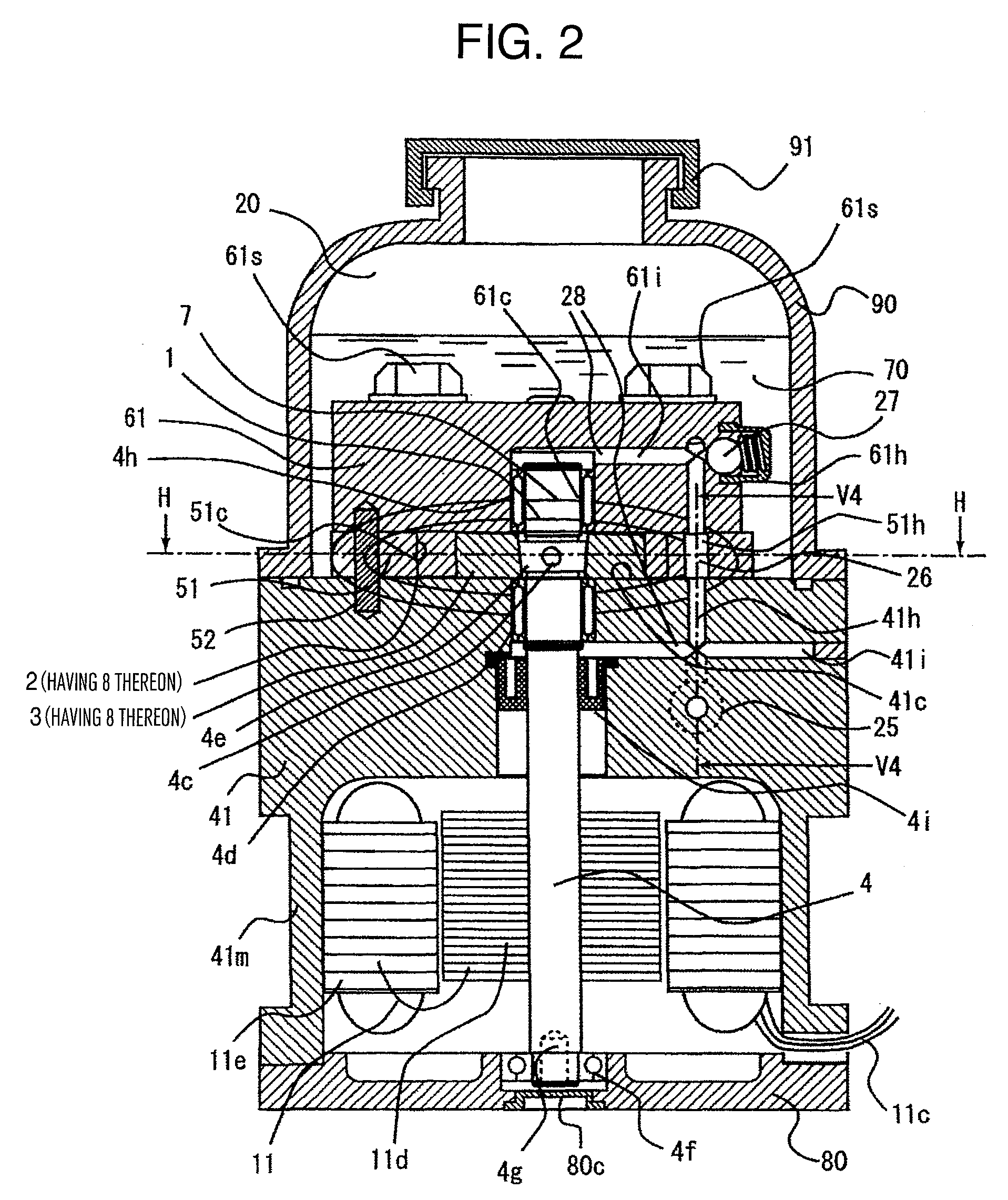
[0035]A description will be given as to a first embodiment of the pump apparatus and the power steering on which the pump apparatus is mounted according to the present invention, based on FIGS. 1 to 13. The type of the pump is an internal gear type and is a reversible pump which drives an electric motor bi-directionally, FIG. 1 is a cross sectional view of an internal gear portion (an H-H cross section of FIG. 2), FIG. 2 is a longitudinal sectional view going through a motor shaft (a V1-V1 cross section of FIG. 1), FIG. 3 is a plan view when internal gears and members placed above those are removed (a casing top view), FIG. 4 is a longitudinal sectional view going through a first port and a second port (a V2-V2 cross section or a V3-V3 cross section of FIG. 3), FIG. 5 is a longitudinal sectional view going through a discharge source switch valve (a V4-V4 cross section of FIG. 2), FIG. 6 is a perspective view of an external gear, FIG. 7 is a perspective view of an internal gear, FIG....

second embodiment

[0091]Next, a second embodiment of the present invention will be described by using FIG. 14.

[0092]This embodiment is the same as the first embodiment except that a discharge pressure lead-in circumferential groove 51q is provided on the housing case 51. Therefore, a description of the configuration and the effects other than those related to the circumferential groove 51q will be omitted.

[0093]The discharge pressure lead-in circumferential groove 51q leads the high-pressure hydraulic oil from the port groove on the high pressure side to the peripheral surface of the internal gear 2. Thereafter, the flow passing along the peripheral surface on the confinement area side is made sure, and the high-pressure hydraulic oil can be securely introduced to the periphery on the confinement area side of the internal gear 2 so as to allow a force in the direction for biasing the sliding contact portion (a biasing force) to be securely exerted. Thus, it realizes the ultimate high pump performance...

third embodiment

[0094]Next, a third embodiment of the present invention will be described by using FIG. 15.

[0095]This embodiment is the same as the aforementioned first embodiment except that a low pressure lead-in path 75 is provided on the smallest pump chamber side ending portion 41p side. Therefore, a description of the configuration and the effects other than those related to the low pressure lead-in path will be omitted.

[0096]As the low pressure lead-in path 75 is a channel for connecting the oil-drain circuit 26 which is constantly at the lowest pressure in the pump apparatus (except the reservoir tank 20) with clearance space of the peripheral surface of the internal gear 2. Therefore, there arises an oil flow such that the hydraulic oil leaked out to the clearance space from the pump chamber passes through this channel and flows out to the oil-drain circuit 26. Here, channel resistance is high because the low pressure lead-in path 75 is a restriction channel, and the pressure lowers in an ...


PUM


Abstract

In order to realize cost reduction in a gear pump apparatus by reducing form accuracy of a gear while securing pump performance, a running-in coating is provided on a tooth sliding contact portion when forming a confinement area in at least one of gears of the gear pump apparatus. By this feature, the running-in coating is gradually worn away and deformed according to rotary drive of the pump, and thus it is possible to obtain an optimal gear form in meshing combinations of the gears. Further, it is possible to reduce leakage inside the pump to secure the pump performance even if the form accuracy of the gear is reduced for the sake of the cost reduction.

Description

BACKGROUND OF THE INVENTION[0001]1. Field of the Invention[0002]The present invention relates to a pump apparatus to be a hydraulic source of a hydraulic power steering for realizing steering of an automobile or the like, and in particular to the pump apparatus capable of suppressing leakage inside a pump and realizing high performance, and the power steering using the same.[0003]2. Description of Related Art[0004]As disclosed in JP-A-2005-41301, a conventional power steering gains a steering assisting force by selectively supplying oil pressure from a reversible pump apparatus driven by an electric motor to respective right and left cylinder chambers of a power cylinder. The reversible pump apparatus is an internal gear pump and realizes a bidirectional pumping action, in which a pump chamber is formed between an external gear which is rotatively driven and an internal gear which is engaged therewith, and its rotation direction is changed to change a moving direction of the pump ch...

Claims


Application Information

Patent Timeline
IPC IPC(8): F04C2/10
CPCF04C2/084F04C2/102F04C2230/91F04C15/0019F04C15/0026F04C2/18
Inventor TSUBONO, ISAMUSASAKI, MITSUOTAKAHASHI, TORUBUSUJIMA, MASAAKIKURATA, MASAKAZUNAKAKUKI, YASUHITO
Owner HITACHI LTD
Why Eureka
Try Eureka