Highly Efficient Material Spraying Type Carbon Nanostructure Synthesizing Method and Apparatus

a carbon nanostructure and high-efficiency technology, applied in carbonsing rags, chemical/physical/physicochemical processes, fulllerenes, etc., can solve the problems of wasteful byproducts, low yield, and method that is not suitable for mass production, so as to reduce the generation of tar-like byproducts and increase the yield of carbon nanostructures. , the effect of high efficiency

Inactive Publication Date: 2007-11-01
JAPAN SCI & TECH CORP +3
View PDF18 Cites 40 Cited by
  • Summary
  • Abstract
  • Description
  • Claims
  • Application Information

AI Technical Summary

Benefits of technology

[0020] The present invention is provided in order to solve the problems, and the first mode of the present invention provides a highly efficient material spraying type carbon nanostructure synthesizing method for synthesizing carbon nanostructures from a material gas in accordance with a catalyst chemical vapor deposition method, wherein a material gas of which the temperature is in a range where no tar-like byproducts are generated is sprayed so as to make contact with a catalyst body in a space that has been heated to within a temperature range for the generation of carbon nanostructures, so that carbon nanostructures are generated. It has been found, as a result of the research conducted by the present inventors, that tar-like byproducts are generated when the material gas decomposes and combines during the process where the temperature gradually increases from a low temperature to a temperature for the generation of carbon nanostructures. That is, the subject matter of the present invention is removal of the middle temperature range where the material gas decomposes and combines from the reaction process. Therefore, according to the present invention, the material gas is maintained within a temperature range (temperature that is lower than the middle temperature range; room temperature a temperature lower than that) where tar-like byproducts are not generated, and this material gas is introduced directly into the temperature range for the generation of carbon nanostructures, skipping the middle temperature, and thereby, it becomes possible to greatly reduce the generation of tar-like byproducts. In addition, the material gas is directly sprayed toward the reaction region, and therefore, the probability of reaction occurring between the catalyst body and the material gas within the reaction region increases, so that the yield in the generation of carbon nanostructures can be greatly increased. Furthermore, the catalyst body is fixed in the reaction region, and the material gas may be sprayed against this catalyst body, or the catalyst body may be supplied from a catalyst body tank or the like to the reaction region, if necessary.

Problems solved by technology

In both cases, however, the yield was low, and the method was not suitable for mass production.
Recently, however, though synthesis in large amounts has been successful, there is a problem, such that wasteful byproducts are generated.
Tar-like byproducts 16 are black and soil the reaction tube, making the task of cleaning troublesome.
At the same time, a problem arises such that the products cannot be cleaned when adhering at locations that cannot be cleaned.
As described above, it has been found that tar-like byproducts of which the amount cannot be ignored are formed on the inner surface of the reaction tube, and the yield in the generation of the carbon nanostructures does not sufficiently increase in conventional synthesizing apparatuses and in accordance with conventional synthesizing methods.

Method used


Image

  • Highly Efficient Material Spraying Type Carbon Nanostructure Synthesizing Method and Apparatus
  • Highly Efficient Material Spraying Type Carbon Nanostructure Synthesizing Method and Apparatus
  • Highly Efficient Material Spraying Type Carbon Nanostructure Synthesizing Method and Apparatus

Examples


example 1

Generation of Carbon Nanocoils

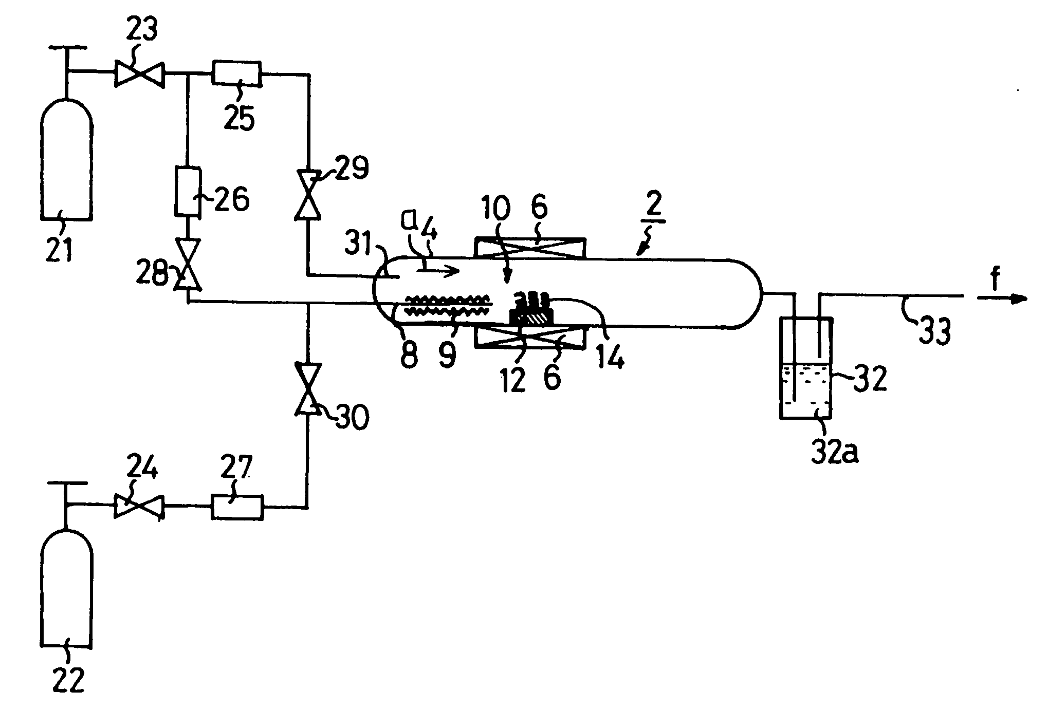
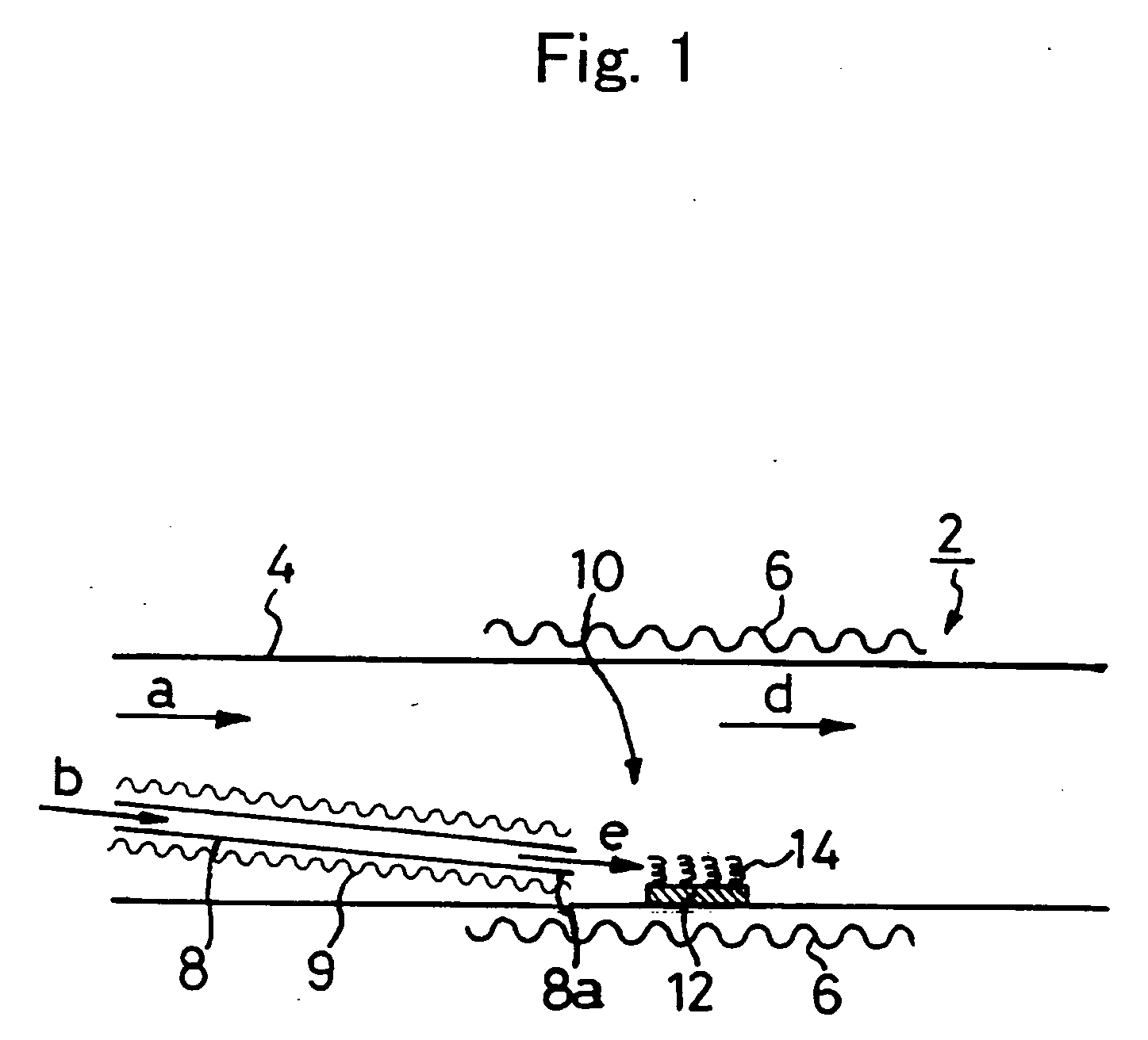
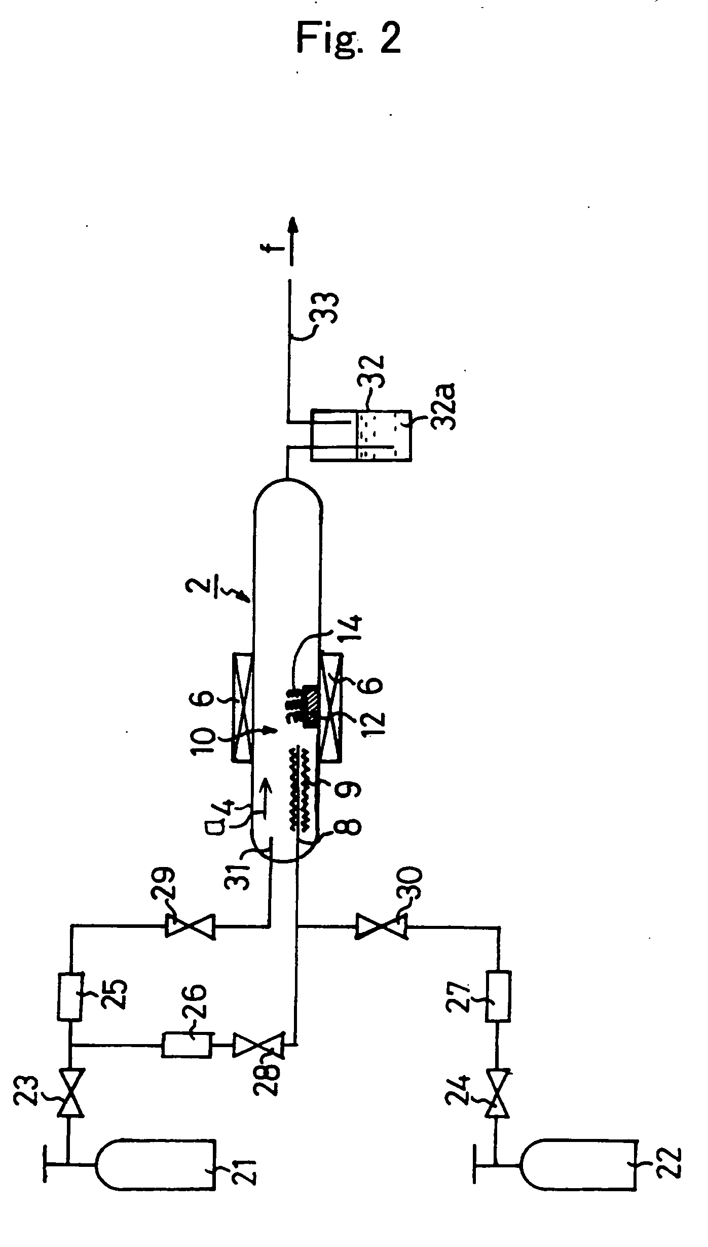
[0091]FIG. 1 is a schematic diagram showing the configuration of a case where a highly efficient material spraying type carbon nanostructure synthesizing apparatus according to the present invention is used for the synthesis of carbon nanocoils. In a highly efficient material spraying type carbon nanostructure synthesizing apparatus 2, a heater 6 for heating a reaction region is placed around the outside of a reaction tube 4, and this heater 6 for heating the reaction region provides a uniform reaction temperature region as a reaction region 10. A catalyst body 12 is placed in this reaction region 10.

[0092] In addition, a material gas supplying pipe 8, having a small diameter, is placed in reaction tube 4, and an end 8a of this supplying pipe reaches the middle of reaction region 10, and in addition, end 8a of the supplying pipe is placed in the vicinity of catalyst body 12. A heater 9 for heating the supplying pipe is placed around the material gas s...

example 2

Carbon Nanotubes

[0119]FIG. 13 is a schematic diagram showing the configuration of a highly efficient material spraying type carbon nanostructure synthesizing apparatus according to the present invention in the case where it is used for the synthesis of carbon nanotubes. This apparatus is a highly efficient material spraying type carbon nanostructure synthesizing apparatus 2 which is exactly the same as that of Example 1, but a catalyst body 12, the temperature of the reaction region, the temperature of the material gas supplying pipe, the material gas and the carrier gas are different.

[0120] The first difference is that a catalyst where Ni is sintered in highly pure γ-alumina pellets (99.95% or more) of which the sodium content is 0.01% or less is used as catalyst body 12. The second difference is that the temperature of the reaction region is maintained at 500° C. The third difference is that the temperature of the material gas supplying pipe is maintained at 250° C. In addition,...

example 3

[0124]FIG. 14 is a schematic diagram showing the configuration of a highly efficient material spraying type carbon nanostructure synthesizing apparatus according to the present invention in the case where a catalyst powder is used as the catalyst body. Though in FIG. 14, catalyst body 12 of FIG. 1 is formed of a catalyst structure, a catalyst powder 13 is made to flow in the direction of arrow a in Example 3. When catalyst powder 13 flows into a reaction region 10, it is heated to the temperature for generating carbon nanostructures by heater 6 for heating the reaction region while a material gas is sprayed against catalyst powder 13 from material gas spraying nozzle 8b so that carbon nanostructures 14 grow on the surface of catalyst powder forming particles 13a.

[0125] Material gas supplying pipe 8 is placed so that material gas spraying nozzle 8b reaches reaction region 10, heater 9 for the material gas supplying pipe is placed around material gas supplying pipe 8, and the entiret...


PUM

PropertyMeasurementUnit
temperatureaaaaaaaaaa

Abstract

Developed are a synthesizing method for carbon nanostructures where the generation of tar-like byproducts is reduced and carbon nanostructures are generated highly efficiently, and a unit therefor. A highly efficient material spraying type carbon nanostructure synthesizing apparatus according to the present invention is formed of a catalyst body that is placed inside a reaction tube, a heating unit that is provided in order to heat the vicinity of this catalyst body to the temperature range where carbon nanostructures are generated, a material gas supplying pipe for introducing a material gas into reaction tube which is provided in such a manner that an end of this supplying pipe is placed in proximity to catalyst body, and a preheating unit for preheating the material gas supplying pipe to a temperature range where no tar-like products are generated from a material gas. No tar-like substance is generated in the material gas supplying pipe, and the material gas is directly sprayed against the catalyst body, skipping the middle temperature range. Therefore, the probability of reaction occurring is high, and the yield in the generation of carbon nanostructures is high. Most of the material gas is consumed; thus, no tar-like substance is generated inside reaction tube.

Description

TECHNICAL FIELD [0001] The present invention relates to a method for manufacturing carbon nanostructures from a material gas in accordance with a catalyst chemical vapor deposition method. More specifically, the present invention relates to a carbon nanostructure synthesizing method and apparatus where carbon nanostructures can be generated highly efficiently from a material gas, and tar-like byproducts that are generated from the material gas can be reduced. BACKGROUND ART [0002] Carbon nanostructures have been attracting attention as a core substance used in nanotechnology. In the present invention, carbon nanostructures are a substance of a nano-size which is formed of carbon atoms, and examples thereof include carbon nanocoils in coil form, carbon nanotubes in tube form, carbon nano-twists which are carbon nanotubes having twists, carbon nanotubes with beads where beads are formed on carbon nanotubes, carbon nano-brushes where carbon nanotubes stand together in large numbers, an...

Claims


Application Information

Patent Timeline
Patent Type & Authority Applications(United States)
IPC IPC(8): C01B31/02D01F9/127
CPCB82Y30/00B82Y40/00C01B31/0293C01B31/0213C01B31/0233C01B31/02C01B32/05C01B32/162C01B32/18C01B32/154
Inventor NAKAYAMA, YOSHIKAZUNAGASAKA, TAKESHISAKAI, TORUHAYASHI, TAKESHITSUCHIYA, HIROYUKILI, XUNOSAKA, TOSHIKAZU
Owner JAPAN SCI & TECH CORP
Why Eureka
Try Eureka