Transmission circuit, and communication apparatus using the same

a transmission circuit and communication apparatus technology, applied in the field of transmission circuits and communication apparatuses using the same, can solve the problems of difficult to output a desired transmission signal sb>0/b, difficult to output a highly linear transmission signal in such an area, and achieve the effect of high efficiency

Inactive Publication Date: 2007-11-01
PANASONIC CORP
View PDF6 Cites 18 Cited by
  • Summary
  • Abstract
  • Description
  • Claims
  • Application Information

AI Technical Summary

Benefits of technology

[0017]Therefore, an object of the present invention is to provide a compact transmission circuit for outputting a highly linear transmis

Problems solved by technology

Therefore, when the output signal s1 or s2 includes a phase error or an amplitude error, it is difficult to output a desired transmission signal s0.
Therefore, a highly linear transmission signal cannot be output in such an area.
The conventional transmission circuit 600 (FIG. 22) has the problem that because a transmission signal s0 is generated by combining two output signals s1 and s2 having different phases, it is difficult to output a desired transmission signal s0 due to a phase error or an amplitude error included in the output signal s1 or s2 as described above.
The conventional transmission circ

Method used


Image

  • Transmission circuit, and communication apparatus using the same
  • Transmission circuit, and communication apparatus using the same
  • Transmission circuit, and communication apparatus using the same

Examples


first embodiment

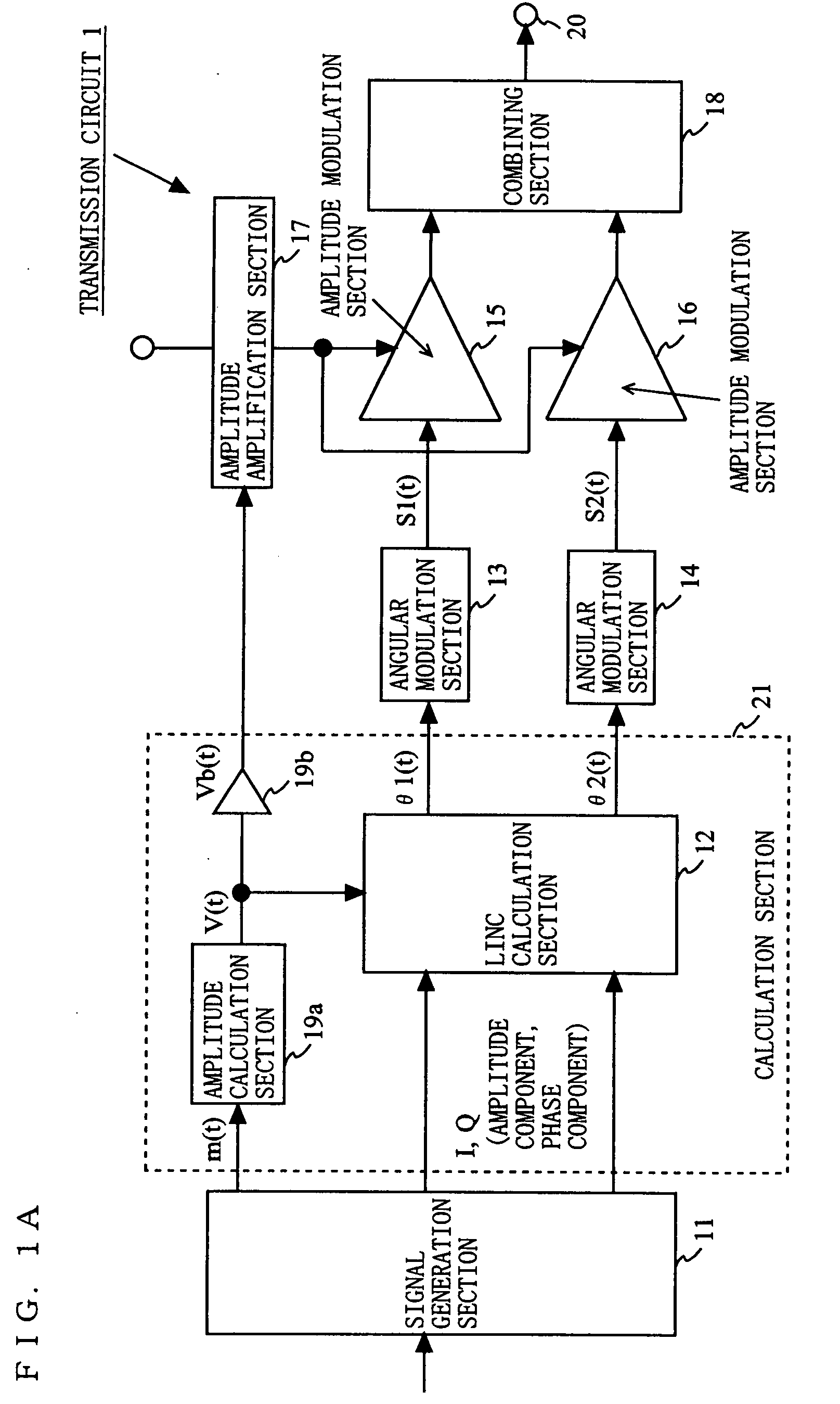
[0076]FIG. 1A is a block diagram showing an exemplary structure of a transmission circuit 1 according to a first embodiment of the present invention. As shown in FIG. 1A, the transmission circuit 1 includes a signal generation section 11, a LINC calculation section 12, an angular modulation section 13, an angular modulation section 14, an amplitude modulation section 15, an amplitude modulation section 16, an amplitude amplification section 17, a combining section 18, an amplitude calculation section 19a, an amplification section 19b, and an output terminal 20. The LINC calculation section 12, the amplitude calculation section 19a and the amplification section 19b may be represented as being included in a calculation section 21.

[0077]The signal generation section 11 modulates input data to generate signals of a predetermined form and an amplitude signal m(t). The signals of a predetermined form are I and Q signals, which are quadrature signals. The amplitude signal m(t) is represent...

second embodiment

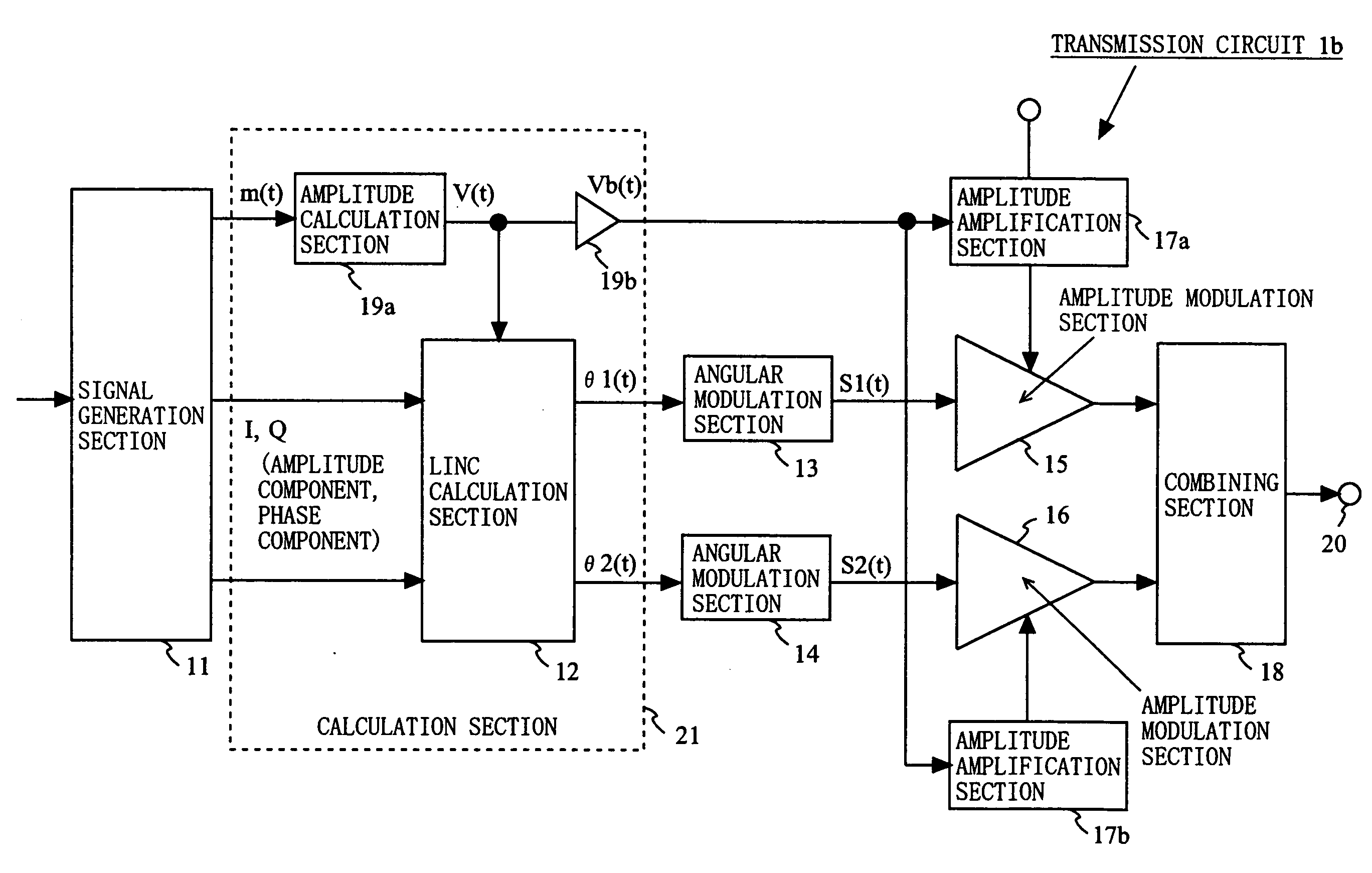
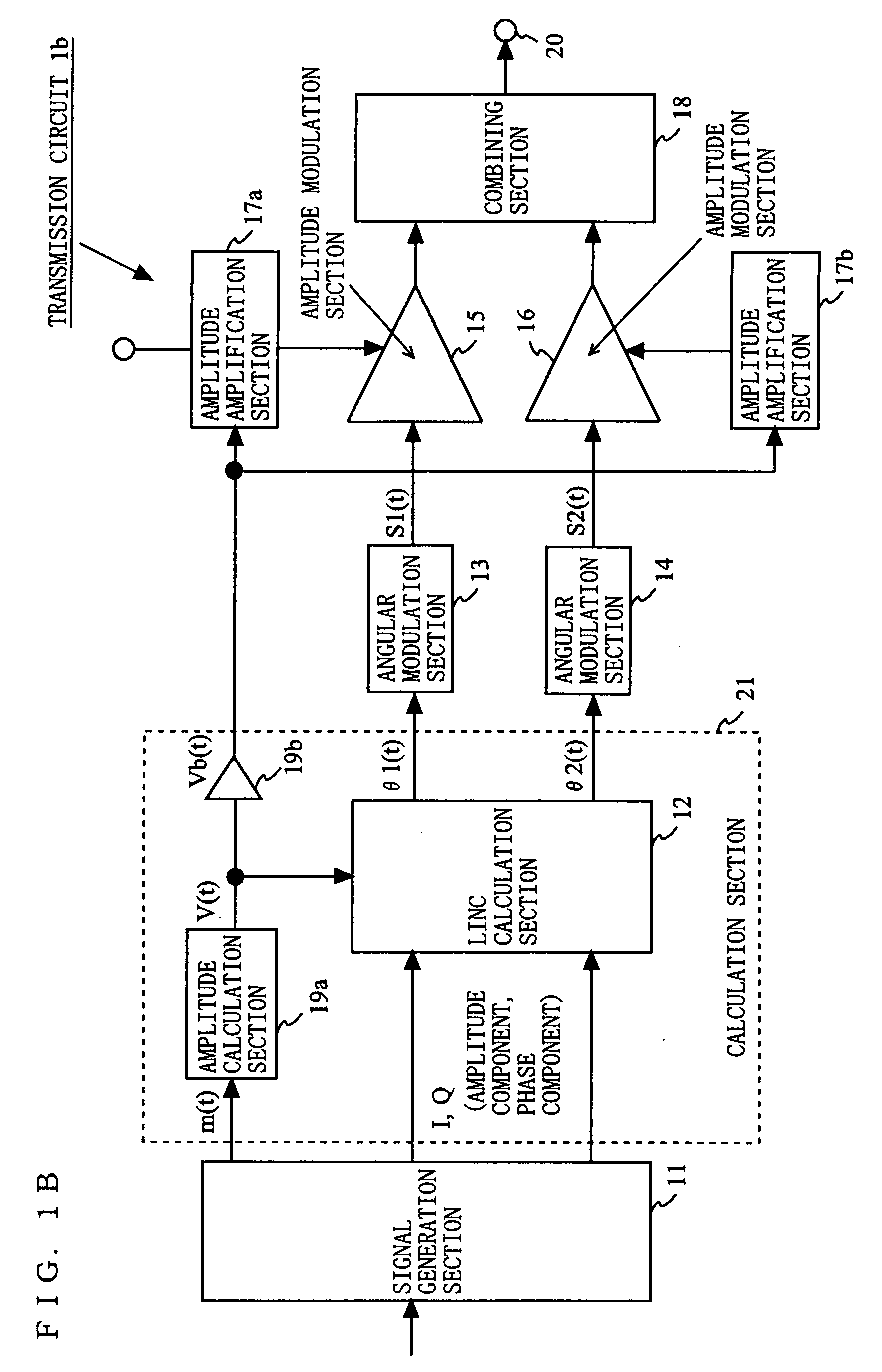
[0111]FIG. 9 is a block diagram showing an exemplary structure of a transmission circuit 2 according to a second embodiment of the present invention. As shown in FIG. 9, the transmission circuit 2 includes a timing control section 22 in addition to the elements included in the transmission circuit 1 according to the first embodiment. The amplitude amplification section 17 includes a series regulator 17a and a switching regulator 17b. The switching regulator 17b supplies a voltage to the series regulator 17a. The series regulator 17a supplies a voltage to the amplitude modulation sections 15 and 16. The series regulator 17a and the switching regulator 17b have the same structures as those shown in FIG. 7A and FIG. 7B.

[0112]FIG. 10 shows an exemplary timing diagram of the signals handled by the transmission circuit 2. With reference to FIG. 10, the transmission circuit 2 according to the second embodiment will be described. To the calculation section 21, an amplitude signal m(t) is in...

third embodiment

[0116]FIG. 11 is a block diagram showing an exemplary structure of a transmission circuit 3 according to a third embodiment of the present invention. As shown in FIG. 11, the transmission circuit 3 includes a variable gain amplification section 23 and a variable gain amplification section 24 instead of the amplitude amplification section 17 included in the transmission circuit 1 according to the first embodiment. To the variable gain amplification sections 23 and 24, a discrete value Vb(t) is input from the calculation section 21. The variable gain amplification section 23 amplifies the first angle-modulated signal S1(t) with a gain in accordance with the level of the discrete value Vb(t). The variable gain amplification section 24 amplifies the second angle-modulated signal S2(t) with a gain in accordance with the level of the discrete value Vb(t). The amplified first angle-modulated signal S1(t) and second angle-modulated signal S2(t) are respectively input to the amplitude modula...


PUM


Abstract

A compact transmission circuit for outputting a highly linear transmission signal regardless of the output power level and operating at a high efficiency is provided. A signal generation section 11 generates an amplitude signal and quadrature data based on input data. A calculation section 21 calculates using the amplitude signal and the quadrature data to output a discrete value having a level discrete at every predetermine time period, and first and second phase signals. An amplitude amplification section 17 outputs a voltage controlled in accordance with the discrete value. Angular modulation sections 13 and 14 angular-modulate the phase signals and output first and second angle-modulated signals. Amplitude modulation sections 15 and 16 amplitude-modulate the angle-modulated signals with the voltage from the amplitude amplification section 17 and output first and second modulated signals. A combining section 18 combines the first and second modulated signals and outputs a transmission signal.

Description

BACKGROUND OF THE INVENTION[0001]1. Field of the Invention[0002]The present invention relates to a transmission circuit used for a communication apparatus such as a mobile phone, a wireless LAN device or the like, and more specifically to a compact transmission circuit for outputting a highly linear transmission signal regardless of the level of the output power and operating at a high efficiency, and a communication apparatus using the same.[0003]2. Description of the Background Art[0004]A communication apparatus such as a mobile phone, a wireless LAN device or the like is required to guarantee the linearity of the transmission signal while operating at a low power consumption whether the communication apparatus may operate at a high output power or a low output power. For such a communication apparatus, a compact transmission circuit for outputting a highly linear transmission signal and operating at a high efficiency regardless of the level of the output power is used. Convention...

Claims


Application Information

Patent Timeline
IPC IPC(8): H04Q7/20
CPCH04B1/0483H03F1/0294
Inventor MATSUURA, TORUISHIDA, KAORU
Owner PANASONIC CORP
Why Eureka
Try Eureka