IC tags/RFID tags for magnetic resonance imaging applications

a magnetic resonance imaging and ic chip technology, applied in the field of radio frequency identification (rfid) tags, can solve the problems of damage or even destruction of the ic chip of the rfid tag, and the traditional rfid tag may not be used in high-power rf field environments

Active Publication Date: 2007-11-08
QUALITY ELECTRODYNAMICS
View PDF4 Cites 55 Cited by
  • Summary
  • Abstract
  • Description
  • Claims
  • Application Information

AI Technical Summary

Benefits of technology

[0011] Such problems are solved, in one non-limiting, exemplary embodiment, by an RFID tag for use with an MRI machine, the RFID tag comprising an integrated circuit, and a structure for protecting the integrated circuit from damage or destruction when the RFID tag is exposed to an RF field from the MRI machine.

Problems solved by technology

This high voltage and / or current may damage or even destroy the IC chip of the RFID tag.
A traditional RFID tag thus may not be used in high strength RF field environments such as MRI applications.

Method used


Image

  • IC tags/RFID tags for magnetic resonance imaging applications
  • IC tags/RFID tags for magnetic resonance imaging applications
  • IC tags/RFID tags for magnetic resonance imaging applications

Examples


Embodiment Construction

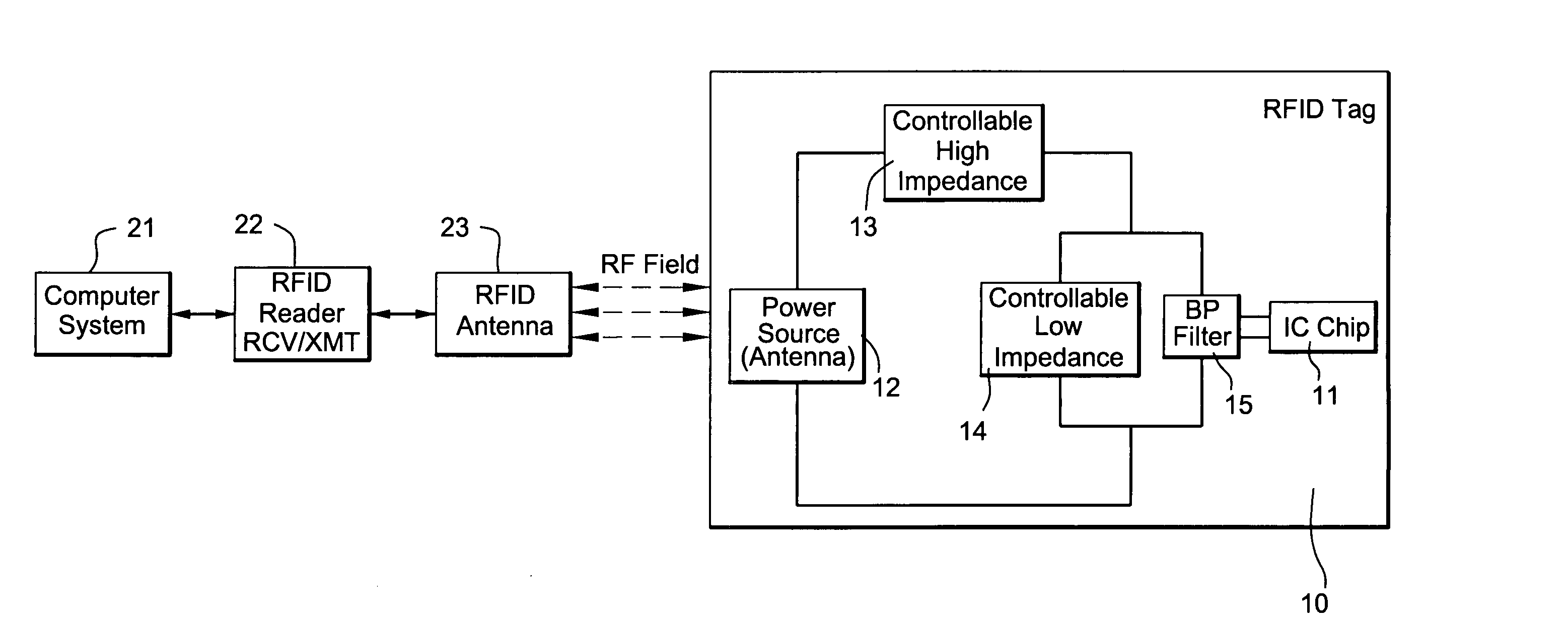
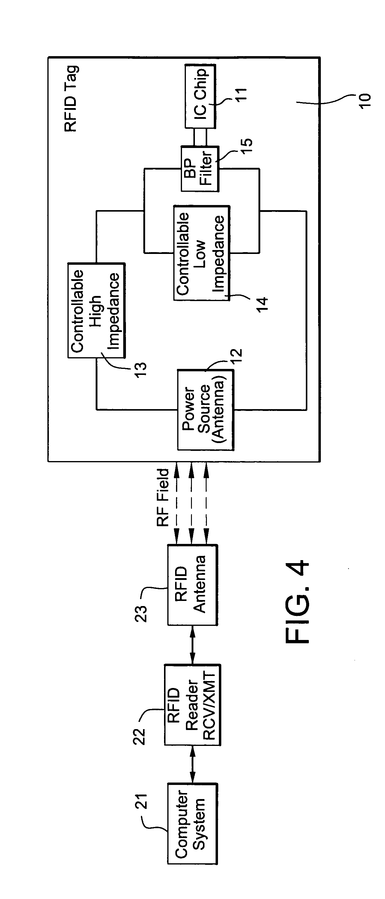
[0037]FIG. 4 illustrates an exemplary RFID tag system which may be used in accordance with one non-limiting, exemplary embodiment. The RFID tag system includes a computer system 21, an RFID reader 22, an RFID antenna 23 and an RFID tag 10. The computer system 21 may be one of a system of computers which control MRI system functions as will be discussed below. Alternatively, the computer system 21 may be a separate additional computer system which communicates with an MRI system computer. The RFID reader 22 transmits and receives RF fields via its corresponding RFID antenna 23 in order to read information stored in the RFID tag 10. In addition to performing a read function, the RFID reader 22 may optionally be able to perform a programming function. That is, in some cases, it may be beneficial to enable the RFID reader 22 to write or read-modify-write data in a memory of the RFID tag 10. On the other hand, a particular RFID tag system may include an RFID reader 22 having only read ca...


PUM


Abstract

An RFID tag for use with an MRI machine has an integrated circuit and structure for protecting it from damage when exposed to an intense MRI RF transmitter field. The structure for protecting the integrated circuit may include a controllable low impedance device coupled across the integrated circuit, a controllable high impedance device coupled in series with the integrated circuit, and/or frequency selective RF filter.

Description

BACKGROUND [0001] 1. Technical Field [0002] Non-limiting, exemplary embodiments relate to a radio frequency identification (RFID) tag for use in an environment of a magnetic resonance imaging (MRI) machine. More particularly, non-limiting, exemplary embodiments relate to a protection device for an RFID tag in an MRI environment so that the RFID tag is not damaged or destroyed by the strong RF fields associated with MRI, and to an apparatus having an MRI machine and an associated RFID tag reading system. [0003] 2. Description of Related Art [0004] RFID technology using parasitic RF receive / transmit circuits is widely used to automatically identify articles. RFID technology possesses numerous advantages over traditional identification technology. For example, because RFID technology uses an RF field to operate, no line of sight is required and because it is powered parasitically by received RF signals it requires no internal battery or other power supply. Also, an integrated circuit (...

Claims


Application Information

Patent Timeline
Patent Type & Authority Applications(United States)
IPC IPC(8): G08B13/14H01Q1/52
CPCA61N1/08G06K19/073A61N2001/086A61N1/086
Inventor YANG, XIAOYUFUJITA, HIROYUKIZHENG, TSINGHUA
Owner QUALITY ELECTRODYNAMICS
Why Eureka
Try Eureka