Information Encoding Method, Decoding Method, Common Multiplier Estimating Method, and Apparatus, Program, and Recording Medium Using These Methods

Active Publication Date: 2007-11-08
NIPPON TELEGRAPH & TELEPHONE CORP
View PDF6 Cites 36 Cited by
  • Summary
  • Abstract
  • Description
  • Claims
  • Application Information

AI Technical Summary

Benefits of technology

[0018] For examples if a sample sequence multiplied by a common gain at the analog level is to be compression-coded, the gain is estimated to be the common multiplier and each sample is divided by the multiplier. As a result, the amplitude is reduced and therefore a conventional coding scheme (for example the scheme described in Non-patent literature 1) can be applied without modification in most cases with a smaller quality loss and a negligibly small increase in the amount of information.
[0019] Because common redundancy in the original sample sequences can be eliminated by the divis

Problems solved by technology

If samples are multiplied by a constant in an analog domain before analog-digital c

Method used


Image

  • Information Encoding Method, Decoding Method, Common Multiplier Estimating Method, and Apparatus, Program, and Recording Medium Using These Methods
  • Information Encoding Method, Decoding Method, Common Multiplier Estimating Method, and Apparatus, Program, and Recording Medium Using These Methods
  • Information Encoding Method, Decoding Method, Common Multiplier Estimating Method, and Apparatus, Program, and Recording Medium Using These Methods

Examples


first embodiment

FIRST EXAMPLE

Coding

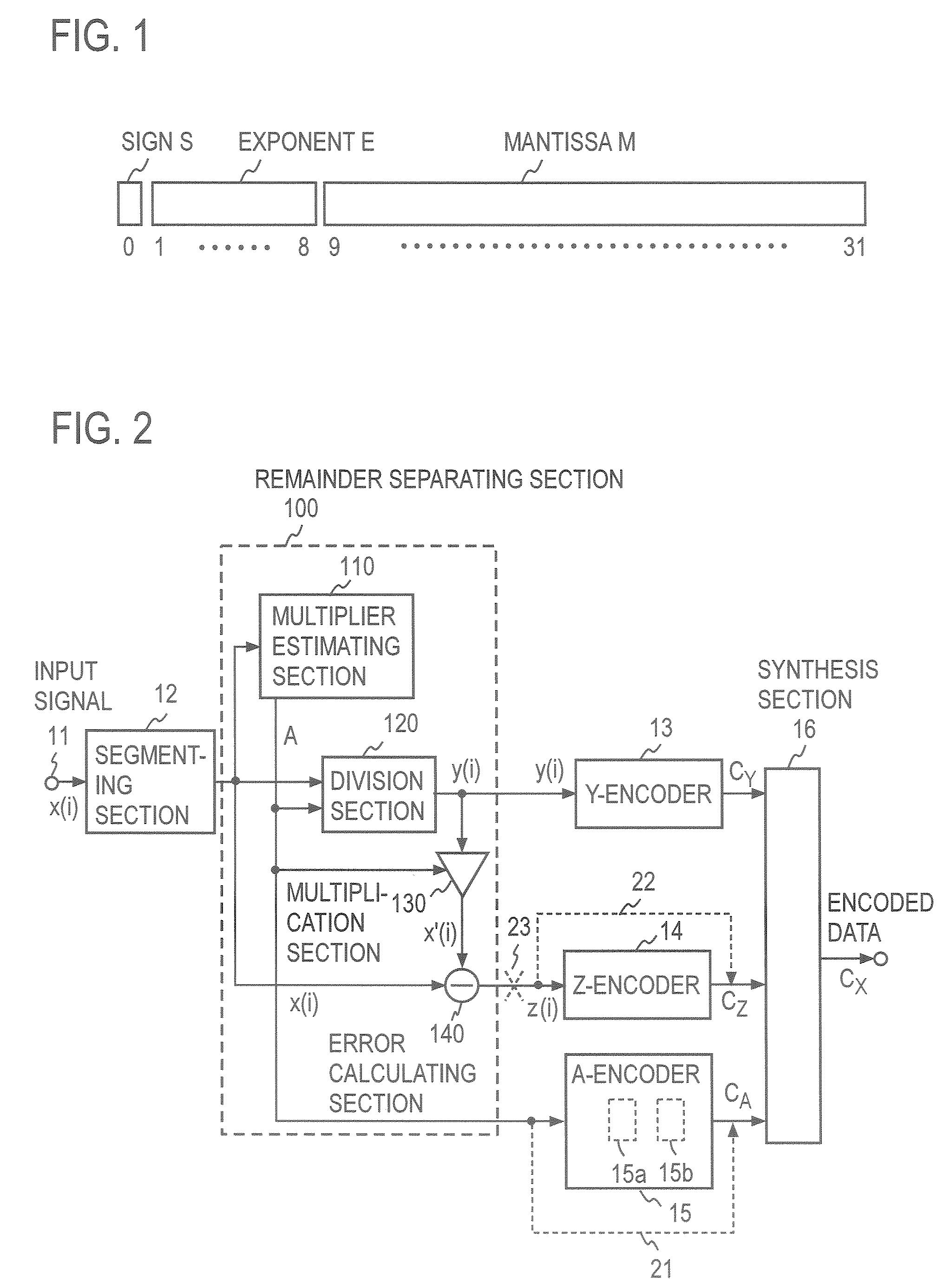
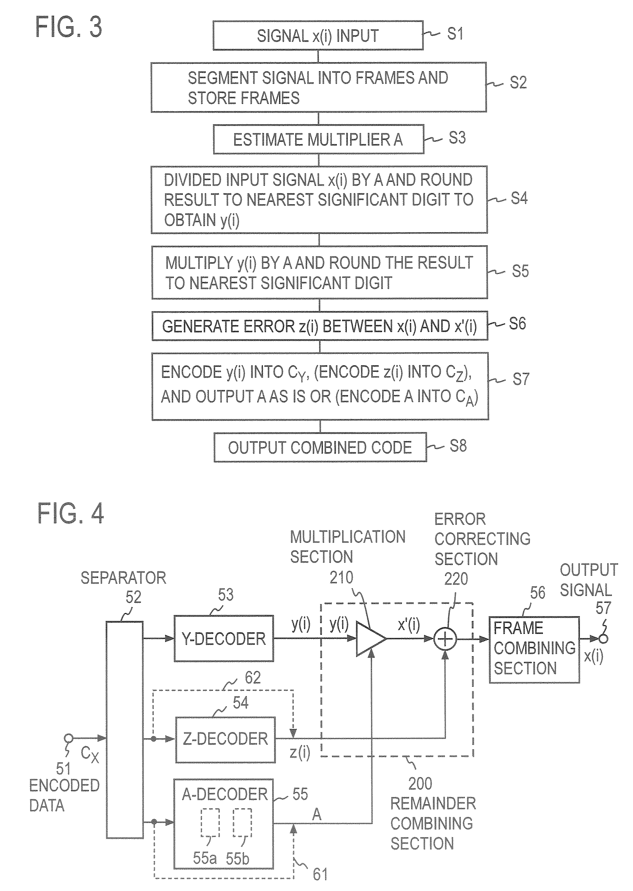
[0070]FIG. 2 shows an exemplary functional configuration of an encoding apparatus according to a first embodiment of the present invention FIG. 3 shows a process performed by the encoding apparatus.

[0071] When an input signal sequence X=(x(0), x(1), . . . ), which is a digitized sample sequence, is inputted t rough an input terminal 11 (step S1), it is divided into sequences consists of a predetermined number N of samples (for example 1,024 samples) in a segmenting (frame) section 12 and temporarily stored in a memory (not shown) (step S2). In the case of an audio signal, the sample sequence may be a integer sample sequence quantized by using a quantifying bit number of 24 bits or a 32-bit single-precision floating-point format sample sequence. In the case of a color video signal, the sample sequence may be a digitized sample sequence of pixel information obtained by raster scanning color information elements into which the color video signal is split.

[0072] ...

second embodiment

THIRD EXAMPLE

Quotient Signal Transformation

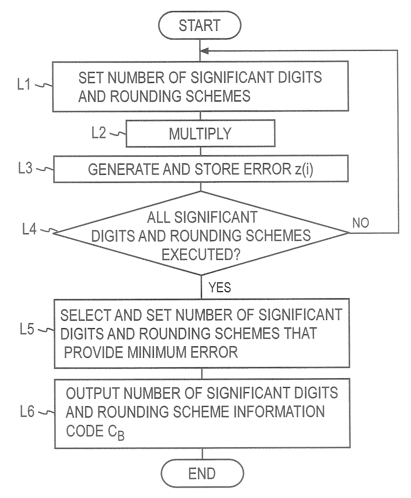
[0105] Another example will be described in which the amount of information of error signals z(i) is reduced by transforming quotient signals y(i). FIG. 11 shows an exemplary configuration of the relevant part used for the transformation and FIG. 12 shows an exemplary process.

[0106] The example differs from the first example (FIG. 2) in that a quotient signal y(i) obtained in a division section 120 is transformed so that the error signal z(i) outputted from an error calculating section 140 in the encoding apparatus is minimized.

[0107] For example, if y(i) is calculated to a predetermined number of significant digits in the division section 120, by rounding down or off to the significant digits, the y(i) contains a round-off error. Similarly when decoded y(i) decoded in the multiplication section 210 is multiplied by a decoded multiplier A in a decoding process in a decoding apparatus (FIG. 4), a round-off error can be produced. The seco...

fourth example

Quotient Signal Transformation

[0117] While quotient signals y(i) are transformed also in a fourth example, the fourth example differs from the third example in that a different measure for evaluation is used to determine y′(i). When a Y-encoder 13 and a Z-encoder 14 use a lossless coding scheme, y(i) is transformed into y′(i) in a transformation section 170 so that the total volume of codes CY and CZ is minimized. For example, the number of significant digits of y′(i) may be varied in a predetermined range to find y′(i) that results in the smallest total size of an output code.

[0118]FIG. 13 shows an exemplary functional configuration of the relevant part and FIG. 14 shows an exemplary process. A quotient signal y(i) from a division section 120 is inputted in a transformation section 170. First, y(i) and its corresponding error signal z(i) are individually encoded (step L21). The volume VY of code CY and the volume VZ of code CZ are added together to obtain the sum (the number of b...


PUM


Abstract

An object of the present invention is to provide a method for encoding signals by separating a signal by using a common multiplier so as to improve the efficiency of compression of audio signals and a method for calculating a common multiplier of a set of numeric values including errors. A common multiplier A, of the input signal samples x(i) in each frame is estimated. Each sample x(i) is divided by A, the quotient is rounded to the number of significant digits, and the rounded quotient y(i) is encoded. The quotient y(i) is multiplied by A and the product is subtracted from x(i) to obtain an error signal z(i), which is then encoded. The multiplier A is encoded and the code of y(i), the code of z(i), and the code of A are combined together and outputted. To estimate the common multiplier, each numeric value is divided by a determined representative value. Irreducible fractions between the maximum positive error and the maximum negative error are obtained by dividing each numeric value by a correct representative value using rational approximation. Among the obtained irreducible fractions, the one having the smallest common denominator of the numeric values is obtained and the common denominator is corrected using the representative value to obtain a common multiplier.

Description

TECHNICAL FIELD [0001] The present invention relates to an information compression-encoding method and decompression-decoding method used for improving the efficiency of transmission or saving the recording capacity when sample values of an audio signal, such as voice and music, and a video signal (hereinafter collectively referred to as an information signal) are transmitted through a communication channel or recorded in information recording media, and to a method for estimating a multiplier common to multiple sets of information used for the information compression encoding, and an apparatus, program, and recording medium using these methods. BACKGROUND ART [0002] There are compression encoding schemes that introduces some distortion of audio signal data (sample values) such as MP3, AAC, and TwinVQ. There are also compression encoding schemes of video information data (sample values), such as JPEG There are lossless coding schemes as well that do not introduce distortion (for exa...

Claims


Application Information

Patent Timeline
IPC IPC(8): H03M7/38H03M13/00H03M7/40G10L19/00
CPCG10L19/035H03M7/30H03M7/24G10L19/265
Inventor HARADA, NOBORUSEKIGAWA, HIROSHIMORIYA, TAKEHIROSHIRAYANAGI, KIYOSHI
Owner NIPPON TELEGRAPH & TELEPHONE CORP
Why Eureka
Try Eureka