High performance jack

a high-performance, jack technology, applied in the direction of printed capacitor incorporation, printed electric component incorporation, coupling device connection, etc., can solve the problem that the split pair will suffer a significant near-end cross-talk (next) problem, and achieve high throughput and performance.

Inactive Publication Date: 2007-11-08
SURTEC INDS
View PDF3 Cites 41 Cited by
  • Summary
  • Abstract
  • Description
  • Claims
  • Application Information

AI Technical Summary

Benefits of technology

[0006] It is an object of the invention to provide a connector jack that includes spring contacts with conductor pairs for plural lines defining an RJ style contact interface for conne

Problems solved by technology

The increasing Internet traffic and the increased complexity and use of web applications has forced network providers and network infrastructure managers to seek enhanced transmission speeds for network equipme

Method used


Image

  • High performance jack
  • High performance jack
  • High performance jack

Examples


Embodiment Construction

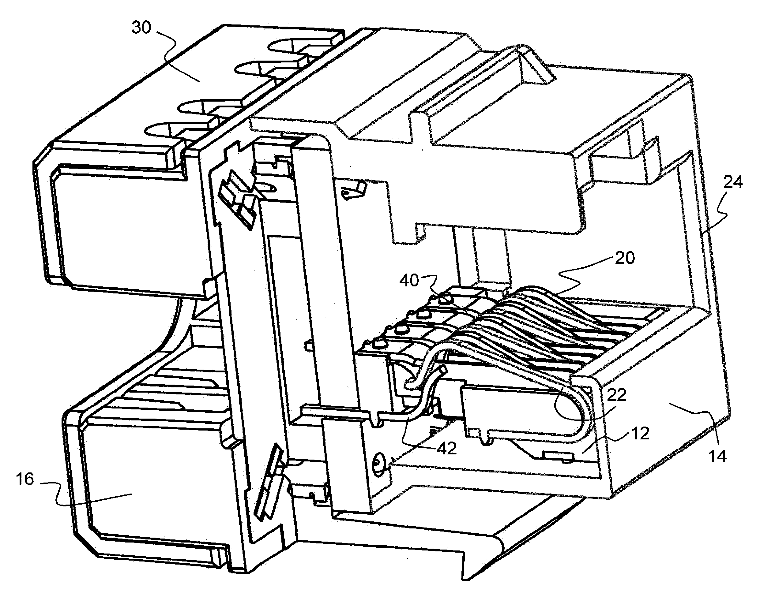
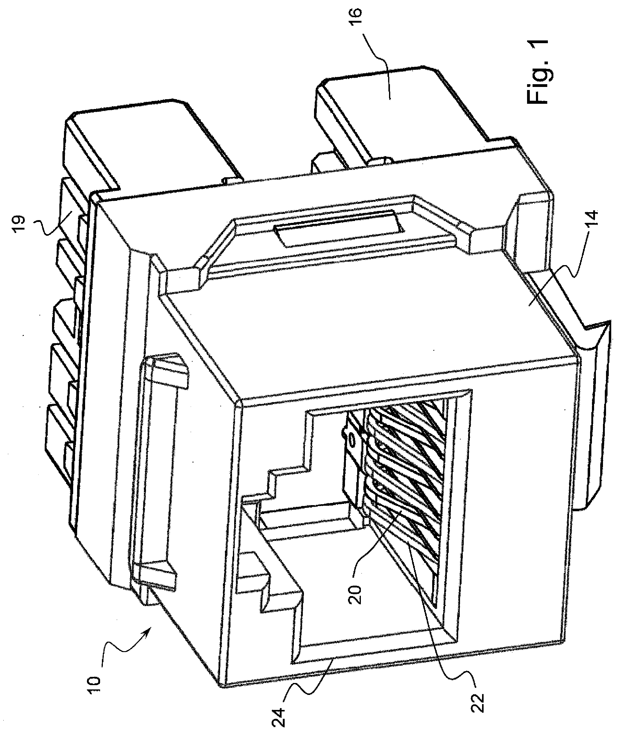
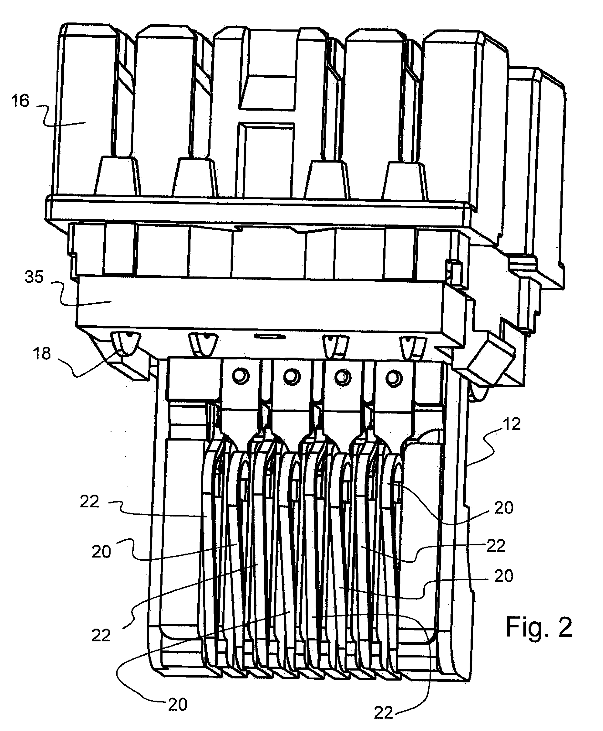
[0038] Referring to the drawings in particular, the invention comprises a high-performance jack. A first embodiment is shown in FIG. 1 with the high-performance jack generally designated 10. The high-performance jack includes a jack body formed with a base part 12 connected to an insulation displacement contact (IDC) part 16 and a cover part 14. FIG. 2 shows the structure with the cover part 14 removed. The cover part 14 defines a plug opening 24 into which a plug 32 may be inserted in a plug insertion direction (having a plug insertion direction axis). The IDC part 16 provides support for IDCs 18 terminated to a circuit board 35. The IDC part 16 has slots 19 for terminating wires in the IDCs 28. This region may be covered with a cover part 30 (FIG. 3).

[0039] The base part 12 supports the circuit board 35 and also supports a plurality of supported spring contact conductors designated 20 and 22. As can be seen in FIGS. 4 and 5, the supported spring contact conductors 20 and 22 are f...


PUM


Abstract

An electrical connector jack is provided including a body with a support portion and a plug receiving portion defining an opening. A circuit board is mounted to the support portion to position the circuit board relative to the plug receiving portion. The circuit board has interconnecting conductor circuit traces respectively extending from spring contact termination locations. A plurality of terminated spring contact conductors is provided with each terminating at a respective one of the spring contact termination locations, each of the terminated spring contact conductors having a contact zone. A plurality of supported spring contact conductors are supported by the body and extend therefrom. The supported spring contact conductors each have a plug contact zone and a terminated spring contact conductor zone. With contact of the plug contact zone with a plug, the supported spring contact conductors are respectively in contact with respective contact zones of the terminated spring contact conductors providing a transmission path from the plug to the circuit traces of the circuit board.

Description

FIELD OF THE INVENTION [0001] The present invention relates to electrical connectors such as RJ style plug and jack connectors for communications systems and more particularly to such connectors which attain a high level of throughput transmission performance such as TIA (Telecommunications Industry Association) / EIA (Electronic Industries Alliance) category six performance (CAT 6) or higher. BACKGROUND OF THE INVENTION [0002] The increasing Internet traffic and the increased complexity and use of web applications has forced network providers and network infrastructure managers to seek enhanced transmission speeds for network equipment. The TIA / EIA set up a high-performance cabling category to fulfill this requirement often referred to as CAT 6. [0003] Such high-performance cabling uses a format with RJ 45 jacks and plugs. The agreed to format for the lines at such a connector involves a line with a center pair of conductors at the connector and a split pair of conductors at the conn...

Claims


Application Information

Patent Timeline
IPC IPC(8): H01R24/00
CPCH01R13/6658H05K1/0228H05K1/162H01R13/6466Y10S439/941H01R13/6474H01R24/64H05K2201/10189
Inventor CHEN, CHOU-HSING
Owner SURTEC INDS
Why Eureka
Try Eureka