Mechanical seal

a mechanical seal and sealing technology, applied in the direction of engine seals, mechanical apparatus, engine components, etc., can solve the problems of degradation of the sealing performance of the mechanical seal, and the degradation of the degradation material on the sliding interface, so as to prevent the degradation of the sealing performan

Active Publication Date: 2007-11-15
KOBE STEEL LTD +1
View PDF8 Cites 15 Cited by
  • Summary
  • Abstract
  • Description
  • Claims
  • Application Information

AI Technical Summary

Benefits of technology

[0017]In the mechanical seal thus configured, the inert gas prevents denaturation, such as oxidation, of the sealing fluid and impurity, thereby preventing generation of the degradation material, or the solvent dissolves therein the degradation material, thereby preventing the deposition thereof. Consequently, the contact pressure between the sliding interface remains unchanged, and the sealing performance can be kept from being degraded.
[0018]Thus, the present invention prevents deposition of the degradation material on an inner edge of the sliding interface, thereby preventing the degradation in sealing performance.

Problems solved by technology

An increase in temperature of the sliding interface because of the friction between the rotating ring and the fixed ring may cause deterioration of the sealing fluid, or may provoke denaturation of impurity such as a process gas dissolved in the sealing fluid, thereby leading to generation of a solid degradation material.
Such degradation material incurs a damage called “blistering” on the sliding interface, once stuck thereon.
The degradation material falsely extends the sliding interface thus to form a secondary sliding interface when stuck to a peripheral region of the sliding interface, which reduces the contact pressure between the rotating ring and the fixed ring, thereby resulting in degraded sealing performance of the mechanical seal.
To prevent the generation of the degradation material, it is effective to reduce the contact pressure or the sliding-contact area between the rotating ring and the fixed ring to thereby reduce the heat generation, however this incurs a disadvantage that the sealing performance is degraded.
This method, however, leads to increased leak of the sealing fluid to a region where the pressure is lower.
Providing the quenching fluid, however, requires an additional equipment, which inevitably leads to an increase in cost.

Method used


Image

  • Mechanical seal
  • Mechanical seal
  • Mechanical seal

Examples


first embodiment

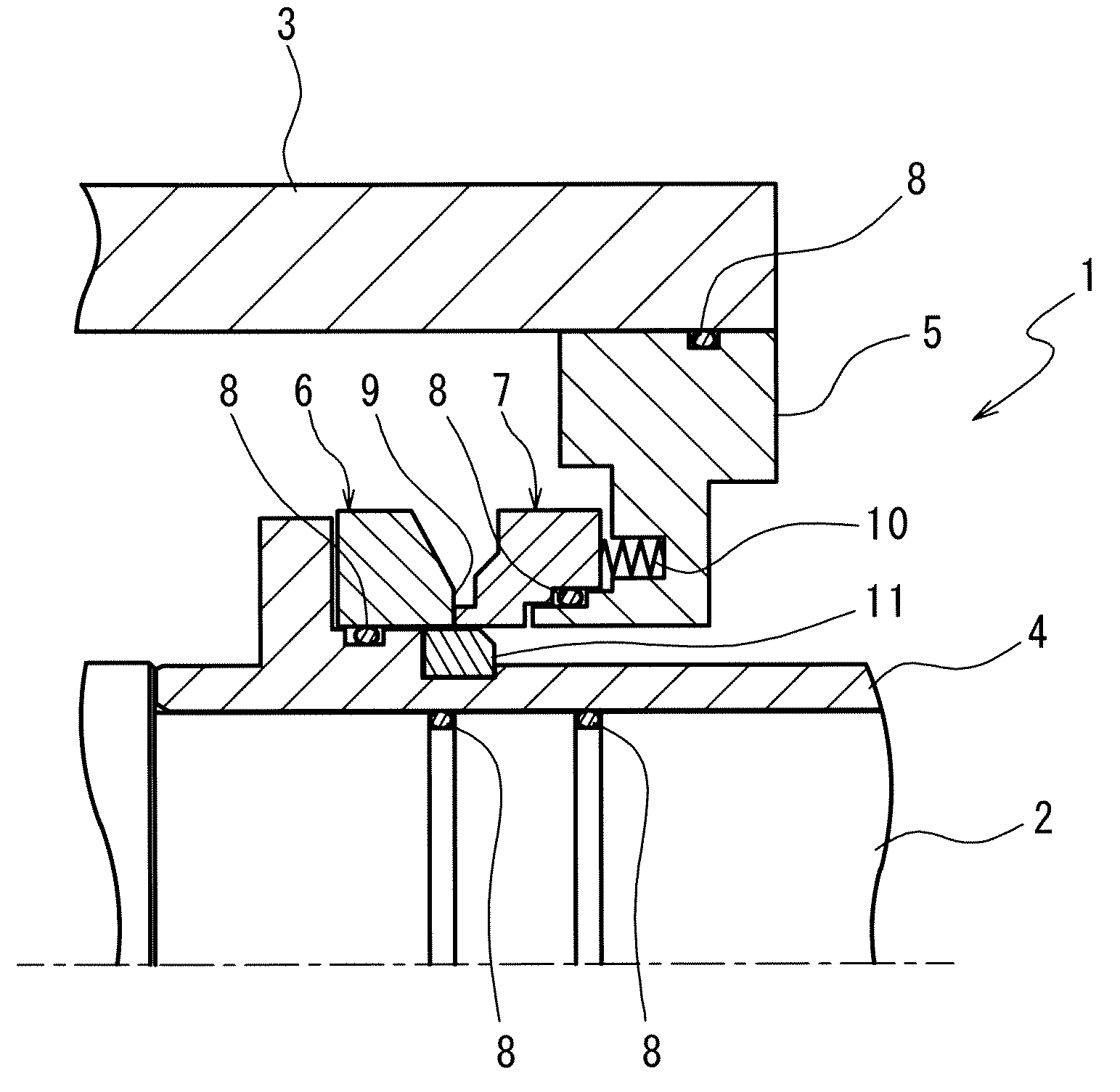
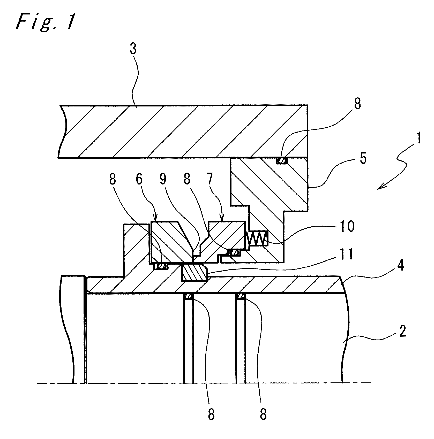
[0027]FIG. 1 is a cross-sectional view showing a mechanical seal 1 according to the present invention. The mechanical seal 1 serves to seal a gap between a rotating shaft 2 and a housing 3 through which the rotating shaft 2 is disposed. The mechanical seal 1 includes a sleeve 4 fitted to an outer circumference of the rotating shaft 2 so as to rotate therewith, a seal cover 5 immovably fixed to the housing 3, an annular rotating ring (mating ring) 6 attached to an outer circumference of the sleeve 4 so as to rotate with the rotating shaft 2, and a fixed ring (seal ring) 7 which is attached to the seal cover 5, slidably in an axial direction but not rotatably.

[0028]The rotating shaft 2, the sleeve 4 and the rotating ring 6 are mutually air-tightly fixed via an O-ring 8, and the housing 3, the seal cover 5 and the fixed ring 7 are also mutually air-tightly fixed via the O-ring 8. The rotating ring 6 and the fixed ring 7 are disposed in sliding-contact with each other at a sliding inter...

third embodiment

[0037]FIG. 3 depicts the mechanical seal 1 according to the present invention.

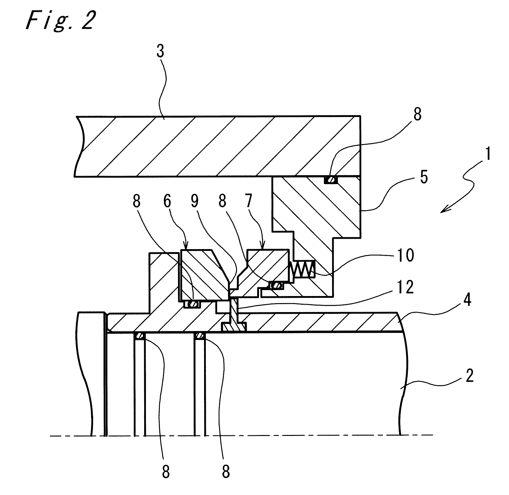
[0038]The mechanical seal 1 of this embodiment includes the pin (scraping member) 12 disposed though the rotating ring 6, instead of through the sleeve 4 as in the second embodiment. The pin 12 is a circular column projecting parallel to the rotating shaft 2 from the rotating ring 6, so as to reach a position close to the inner wall of the fixed ring 7, and serves to scrape off, as the scraping member 11 of the first embodiment and the pin 12 of the second embodiment, the deposited degradation material about to grow from the sliding interface 9 toward an inner region, thereby preventing the formation of the secondary sliding interface.

fourth embodiment

[0039]FIG. 4 depicts the mechanical seal 1 according to the present invention.

[0040]The mechanical seal 1 according to this embodiment includes, instead of a device that scrapes off the degradation material, a discharge screw 13 constituted of a helical protrusion formed around an outer circumferential surface of the sleeve 4. The rotating shaft 2 of this embodiment rotates in a right direction when viewed from the side of the seal cover 5 (right side in FIG. 4).

[0041]The discharge screw 13 is a discharging structure that can convert the rotational force into an axial force with a pressure angle, so as to screw forward the lubricant fluid that has leaked out of the sliding interface 9 along the sleeve 4 with the rotation thereof, thus discharging the lubricant fluid out of the housing 3. The configuration according to this embodiment quickly discharges outwardly the lubricant fluid that has leaked out of the sliding interface 9, without permitting the lubricant fluid to remain on th...


PUM


Abstract

A mechanical seal that prevents deposition of a degradation material generated on a sliding interface is to be provided. In a mechanical seal including a sleeve that rotates with a rotating shaft, a seal cover fixed to a housing, a rotating ring attached to the sleeve and a fixed ring attached to the seal cover and disposed in sliding-contact with the rotating ring via a sliding interface perpendicular to the rotating shaft, a scraping member is provided on the sleeve at a position close to an inner edge of the sliding interface so as to remove a degradation material from the inner edge of the sliding interface. Alternatively a discharging structure is formed on the sleeve so as to discharge the fluid stuck to the sleeve 4 to outside of the seal cover by the rotation of the sleeve. Otherwise, a solvent or an inert gas may be filled in a space defined by the sleeve 4, the rotating ring 6, the fixed ring 7 and the seal cover 5.

Description

FIELD OF THE INVENTION[0001]The present invention relates to a mechanical seal.BACKGROUND OF THE INVENTION[0002]A mechanical seal that seals a gap between a rotating shaft and a housing thereof is to be manufactured according to Generals Rules of JIS-B2405. The mechanical seal includes a rotating ring which is air-tightly attached to a sleeve fitted to an outer circumference of the rotating shaft so as to rotate therewith, and rotates with the sleeve, and a fixed ring which is air-tightly attached to a seal cover fixed to the housing, and does not rotate. The rotating ring and the fixed ring are disposed in sliding-contact with each other at a sliding interface oriented perpendicular to the shaft, and constitute a seal ring in which one is a mating ring immovably disposed in an axial direction and the other is movable in an axial direction and biased by a spring so as to be pressed against the mating ring.[0003]In the mechanical seal, a sealing fluid such as a lubricant provided on ...

Claims


Application Information

Patent Timeline
Patent Type & Authority Applications(United States)
IPC IPC(8): F16J15/38
CPCF16J15/3404F16J15/34F16J15/44F16J15/443
Inventor OHAMA, TAKAOAMANO, YASUSHITSUBONO, HAJIMEAKIYAMA, KOUJITAKAHASHI, HIDEKAZU
Owner KOBE STEEL LTD
Why Eureka
Try Eureka