Stator for an electrical machine

a technology for electrical machines and stabilizers, which is applied in the direction of windings, dynamo-electric components, and magnetic circuit shapes/forms/construction, etc., can solve the problems of complex design of linking conductors, and achieve the effect of simple manufacturing

Inactive Publication Date: 2007-11-15
ZF FRIEDRICHSHAFEN AG
View PDF14 Cites 12 Cited by
  • Summary
  • Abstract
  • Description
  • Claims
  • Application Information

AI Technical Summary

Benefits of technology

[0007]An object of the present invention is to provide a stator having a wiring arrangemen

Problems solved by technology

The figures of U.S. Pat. No. 6,369,473 described above show that the linking conductors have a very complicated design and t

Method used


Image

  • Stator for an electrical machine
  • Stator for an electrical machine
  • Stator for an electrical machine

Examples


Embodiment Construction

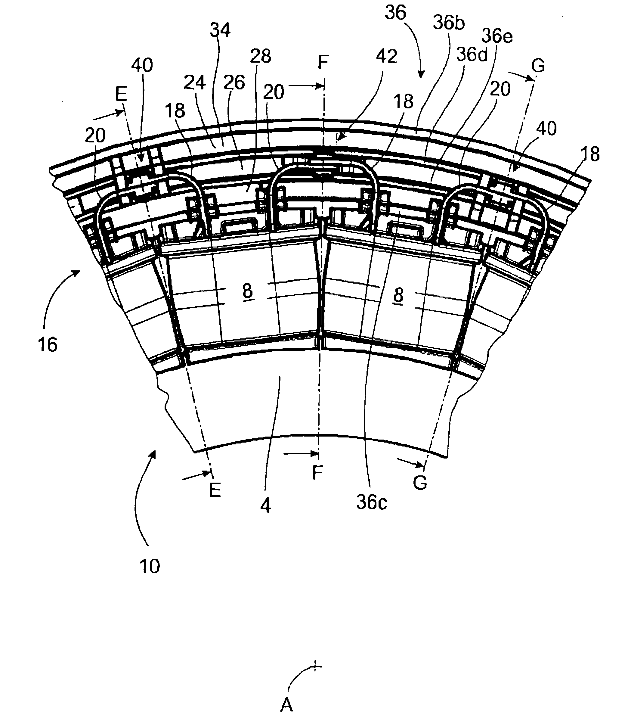
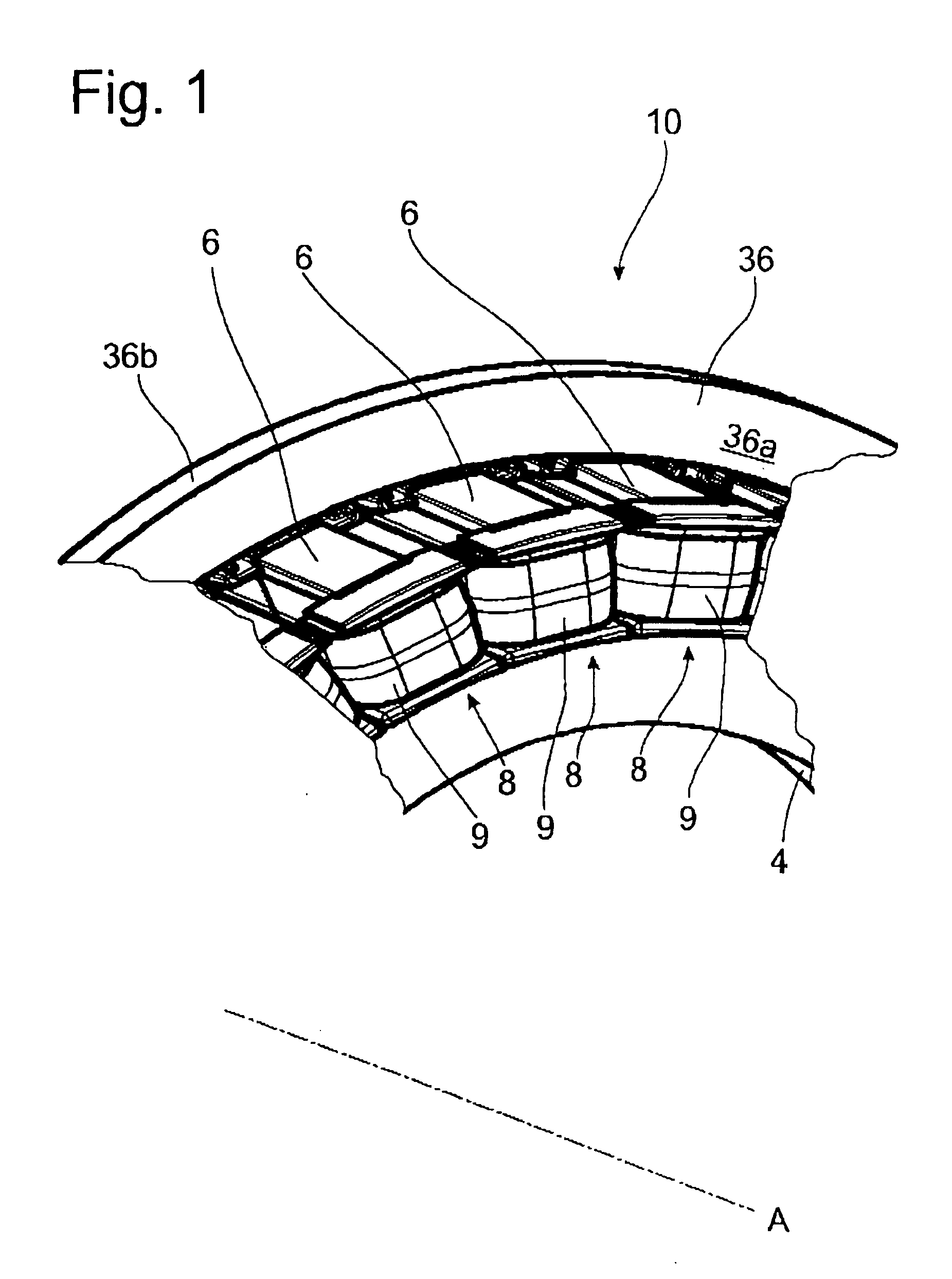
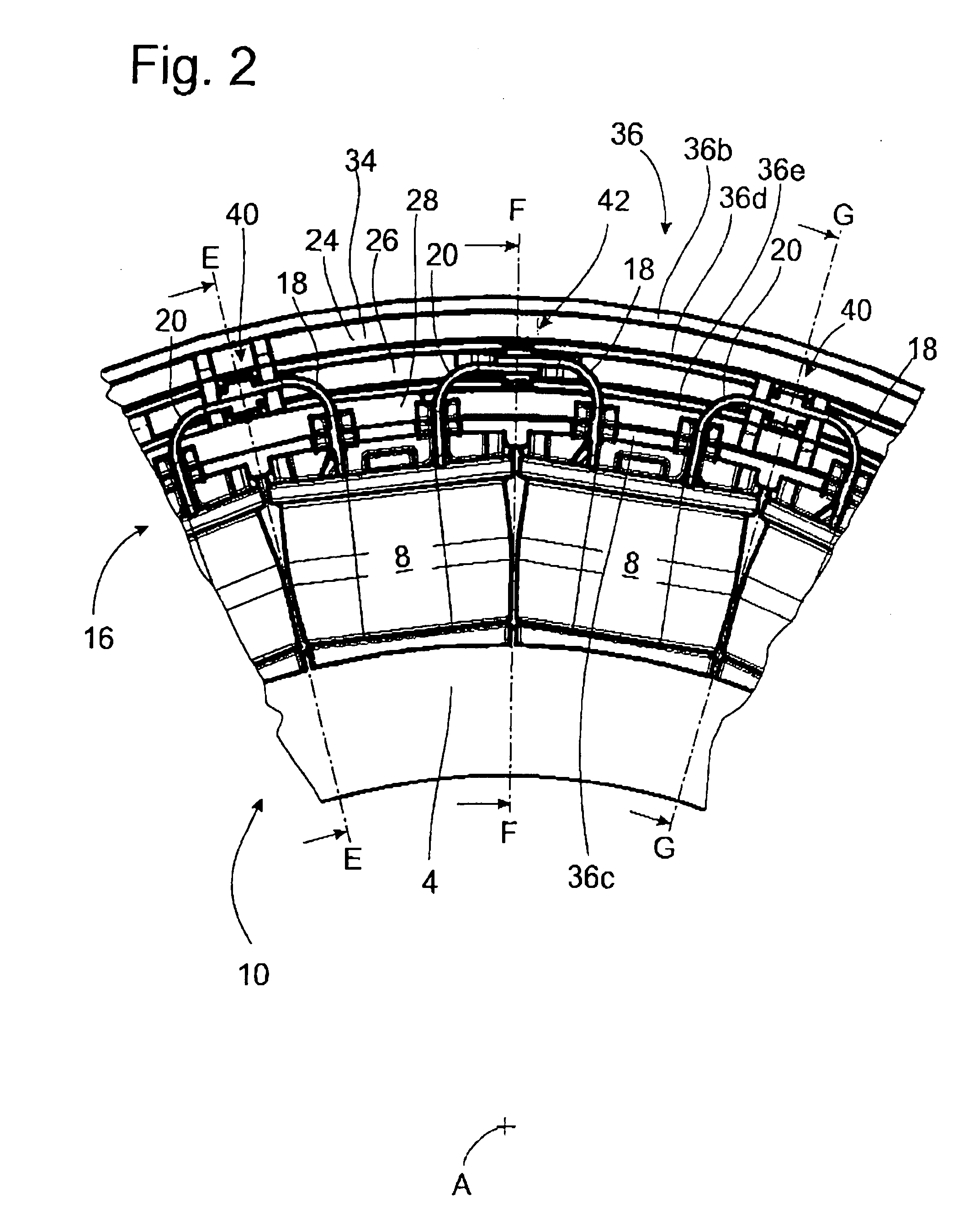
[0020]FIGS. 1-3 show part of a stator 10 for an electrical machine (not shown) with a ring-shaped stator yoke 4 consisting of electric steel laminations and with a rotor 5 (the rotor 5 is schematically indicated in FIG. 3) having a rotor carrier 5a and permanent magnets 5b. The stator of FIGS. 1-3 is designed for a synchronous electrical machine of the external rotor type excited by permanent magnets. However, the specific design of the electrical machine is irrelevant to the following explanation. The machine could be, for example, an induction motor, a reluctance machine of the internal, external, or disk rotor type, or any other type of electrical machine. The stator yoke 4 has a number of radially outward-oriented teeth 6 distributed uniformly around the circumference. Each tooth 6 carries an individual coil 8. Only three or four coils adjacent to each other on the stator are shown in the figures to facilitate a description of the wiring arrangement. The coils 8 include windings...


PUM


Abstract

A stator for an electrical machine includes a ring-shaped stator yoke with a number of stator coils arranged thereon. The conductor ends of the coils are designed to be connected to a wiring arrangement, where the wiring arrangement has linking conductors, which are arranged concentrically to each other, are insulated electrically against each other, and have terminal elements to form electrical contact areas by which they are connected to the ends of the stator coils. The ends of the coils be connected to the linking conductors by separate terminal elements which have a first contact area for establishing a connection with the linking conductor and a second contact area for establishing a connection with at least one coil end.

Description

BACKGROUND OF THE INVENTION[0001]1. Field of the Invention[0002]The present invention pertains to a stator for an electrical machine with a ring-shaped stator yoke having a plurality of stator coils arranged thereon, the stator coils having conductor ends electrically connected to linking conductors concentrically arranged and electrically insulated from each other.[0003]2. Description of the Related Art[0004]Stators for electrical machines are known which include a stator yoke with a plurality of stator teeth and electrical windings in the form of, for example, individually wound stator coils of insulated wire, arranged on each of the teeth. The two conductor ends of each coil are assigned to individual strands, and the coils are connected to each other in a predetermined manner by common linking conductors. In the case of a three-phase machine, the stator has three strands and thus at least three linking conductors, each of which is supplied with current with a phase offset of 120...

Claims


Application Information

Patent Timeline
IPC IPC(8): H02K11/00H02K3/00H02K1/12
CPCH02K3/522
Inventor NIEHAUS, UDOGEHRING, ALEXANDERZIMMER, MANFRED
Owner ZF FRIEDRICHSHAFEN AG
Why Eureka
Try Eureka