Plasma display panel with low voltage material

a technology of plasma display panel and low voltage material, which is applied in the direction of gas discharge filling, electric discharge tubes, electrical apparatus, etc., can solve the problems of low luminous efficacy of pdp (compared to fluorescence lamps), low efficiency of uv generation from discharge, and the importance of pdps luminous efficacy, etc., to achieve the effect of improving the luminous efficacy of plasma display panels

Inactive Publication Date: 2007-11-15
PANASONIC CORP
View PDF16 Cites 16 Cited by
  • Summary
  • Abstract
  • Description
  • Claims
  • Application Information

AI Technical Summary

Benefits of technology

[0030] An object of the present invention is to create a new protective layer operating in a lower voltage (compared to conventional MgO protective layer) for improving luminous efficacy of plasma display panels (PDP).

Problems solved by technology

The luminous efficacy of PDPs is very important issue for plasma TV application.
The low luminous efficacy of PDP (compared to fluorescence lamp) is mainly due to the lower efficiency of UV generation from the discharge.
It is clear the regular MgO film can not meet the criteria because the MgO band gap is too big.

Method used


Image

  • Plasma display panel with low voltage material
  • Plasma display panel with low voltage material
  • Plasma display panel with low voltage material

Examples


example 1

[0069] The newly developed BaxMg1-xO (0.01xMg1-xO instead of MgO film was fabricated in different gas mixture.

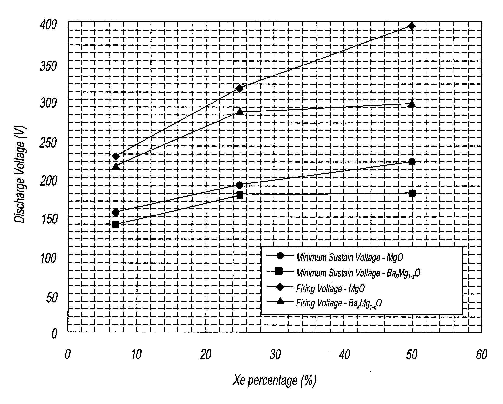
[0070] Referring to FIG. 6, the discharge voltage of a test panel with newly developed BaxMg1-xO layer in different Ne—Xe gas mixture and its comparison to normal MgO layer is shown.

[0071] In FIG. 6, the minimum sustain voltage of BaxMg1-xO layer is 15V to 40V lower than conventional MgO layer from 7% to 50% Xe—Ne gas mixture. The firing voltage difference between BaxMg1-xO and MgO is even more significant, the reduction of firing voltage of BaxMg1-xO layer are 13V at 7% Xe, 30V at 25% Xe, and 100V at 50% Xe.

[0072]FIG. 7 shows relative luminous efficacy of a test panel with newly developed BaxMg1-xO layer in different Ne—Xe gas mixture and their comparison to conventional MgO layer. The luminous efficacy is normalized to the efficacy of a test panel with conventional MgO layer in 7% Xe—Ne gas mixture. Compared to conventional MgO layer, the luminous efficacy of a test pan...

example 2

[0074] Another example of low voltage protective layer is CaxMg1-xO (0.01xMg1-xO (0.01xMg1-xO film instead of MgO film were fabricated with 15% Xe—Ne gas mixture. Hydroxide and carbonate formation can be prevented from forming on CaxMg1-xO by sealing the panel in a moisture and CO2 free environment.

[0075]FIG. 8 shows minimum sustain voltage of 13″ test panels with various newly developed CaxMg1-xO layer in 15% Xe—Ne gas mixture and their comparison to a normal MgO panel with same gas mixture. There is 20V to 25V reduction of minimum sustain voltage in those CaxMg1-xO panels compared to a conventional MgO panel.

[0076]FIG. 9 shows the luminous efficacy of CaxMg1-xO panel can be as high as 2.02 lum / W (in case of CaxMg1-xO-3), 40% higher than the efficacy of a conventional MgO panel (1.44 lum / W). CaxMg1-xO-1, CaxMg1-xO-2, and CaxMg1-xO-3 represents different mixture of CaO and MgO in CaxMg1-xO layer.


PUM


Abstract

A gas discharge device having a plurality of electrodes; and a low voltage protective layer deposited onto the electrodes such that the plurality of electrodes and the low voltage protective layer form a vessel containing a dischargeable gas so that at least the low voltage protective layer is exposed to the dischargeable gas. Also provided is a plasma display panel, including a front plate having scan electrodes and sustain electrodes for each row of pixel sites; a back plate having a plurality of column address electrodes disposed thereon; a dielectric layer covering the column address electrodes; a plurality of barrier ribs disposed above the dielectric layer separating the column address electrodes and being in spaced adjacency therewith; a red phosphor layer, a green phosphor layer and blue phosphor layer sequentially disposed on top of the dielectric layer between the barrier ribs; and a low voltage protective layer deposited on top of dielectric layer that covers the scan electrodes and sustain electrodes on the front plate such that the front plate and the back plate form a panel containing a dischargeable gas so that at least the low voltage protective layer and the phosphor layers are exposed to the dischargeable gas.

Description

BACKGROUND OF THE INVENTION [0001] 1. Field of the Invention [0002] The present invention relates to a gas discharge device having a plurality of electrodes and a low voltage protective layer deposited onto the electrodes. More particularly, the present invention relates to a plasma display panel, which includes a front plate having scan electrodes and sustain electrodes covered by dielectric layer and a low voltage protective layer; a back plate having a plurality of column address electrodes; a dielectric layer; a plurality of barriers; and red, green and blue phosphor layers. [0003] 2. Description of the Related Art [0004] Most commercial plasma display panels (PDP's) are of the surface discharge type. The constitution of a plasma display panel of the prior art is described below with reference to the accompanying drawing. [0005]FIG. 1 is a perspective view of a portion of a conventional AC color plasma display panel. AC PDP includes a front plate assembly and a back plate assemb...

Claims


Application Information

Patent Timeline
Patent Type & Authority Applications(United States)
IPC IPC(8): H01J17/49
CPCH01J11/40H01J11/12H01J11/50
Inventor YAN, QUNGRIES, GEORGE H. JR.CLAUSEN, NORMAN H.
Owner PANASONIC CORP
Why Eureka
Try Eureka