
Magnetic Resonance Imaging Magnet Assembly System with Improved Homogeneity

a magnetic resonance imaging and magnet assembly technology, applied in the field of magnet system for magnetic resonance imaging (mri) system, can solve the problems of inhomogeneity and non-uniformity of the magnetic field, the minimum allowable size of the patient bore, and the separation of the primary and secondary coil units, so as to increase the homogeneity of the superconducting main magn

Inactive Publication Date: 2007-11-15
HITACHI MEDICAL SYSTEMS AMERICA INC
View PDF11 Cites 7 Cited by
  • Summary
  • Abstract
  • Description
  • Claims
  • Application Information

AI Technical Summary

Benefits of technology

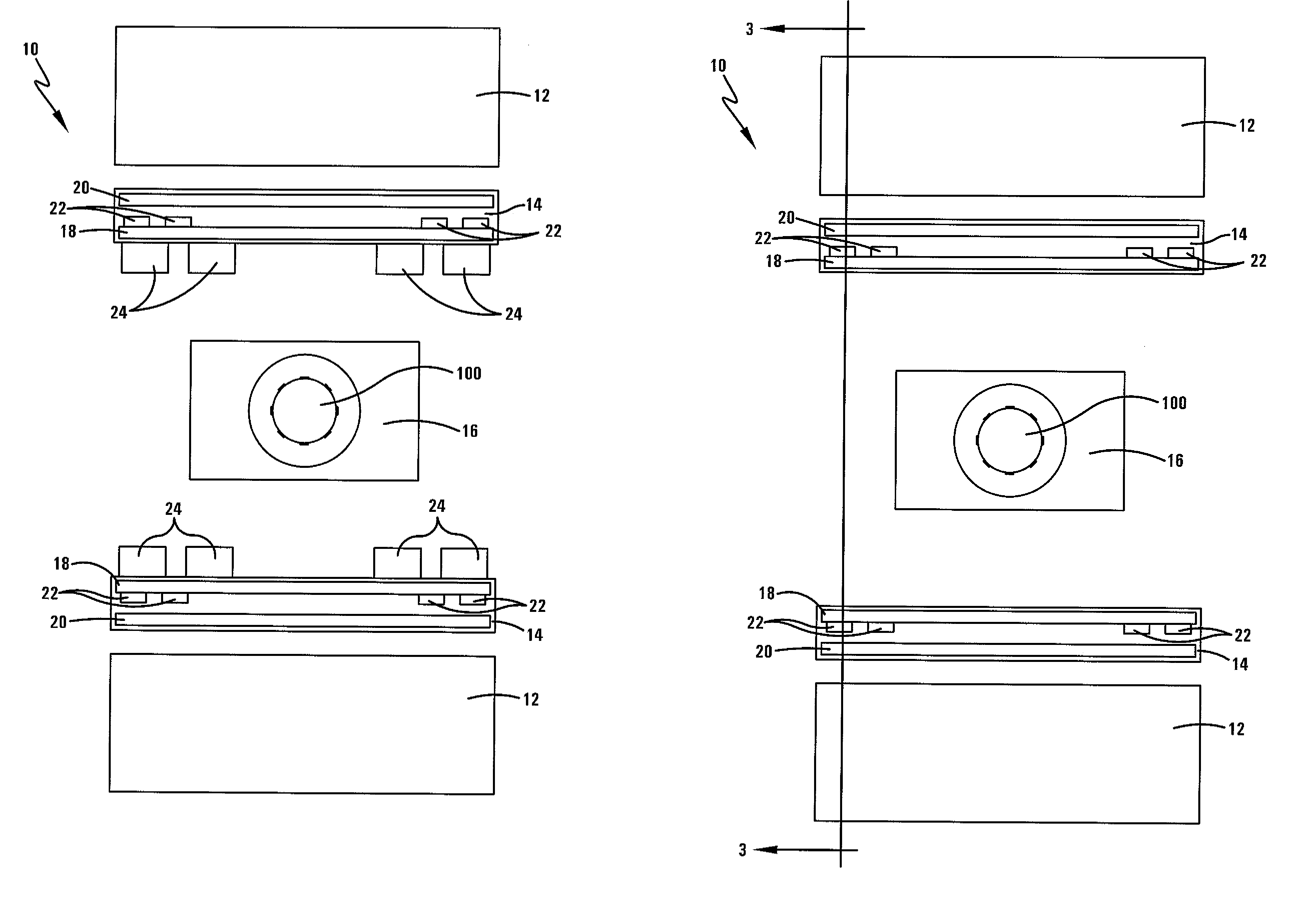
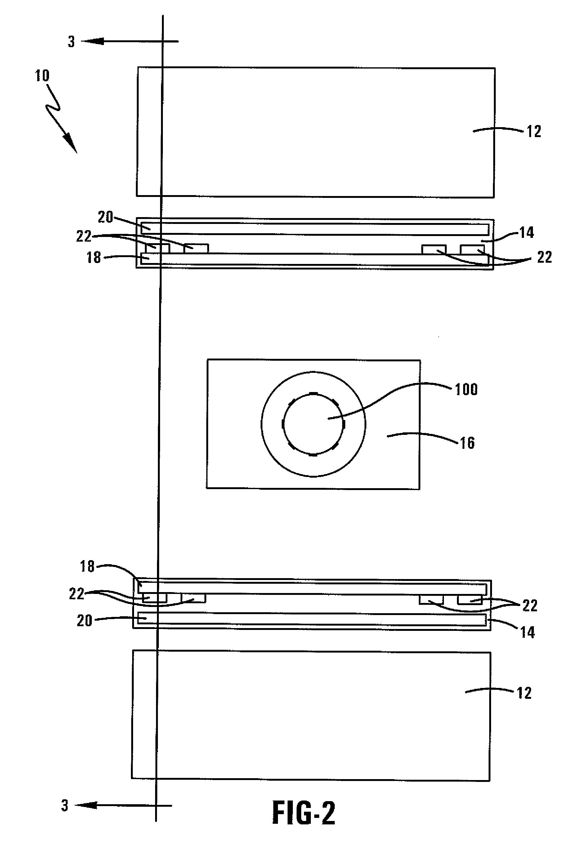
[0017] The above described need is met by adding magnet coil booster packs in unused space within the gradient coils and / or within the unused space between the gradient coils and RF coils for the purpose of increasing the homogeneity of the superconducting main magnet of the magnetic resonance imaging (MRI) system.
[0019] It is another object of this invention to describe an MRI magnet system having coil booster packs or coil bundles positioned in previously unused space within the gradient coils, between the gradient coils and RF coil, or at the ends of the bore to maintain the homogeneity of the previous magnet system while reducing the size of the mechanical structure of the magnet.
[0020] It is a further object of this invention to describe an MRI magnet system utilizing coil booster packs that maintain the size of the magnet system, while improving the homogeneity of the magnetic field.
[0021] It is yet another object of this invention to describe an MRI magnet system utilizing coil booster packs to create a smaller magnet, thus reducing the cost of manufacturing the magnet and easing installation of the magnet.

Problems solved by technology

The larger the gap the more efficient the gradient coil is, however limitations on the minimum allowable size for the patient bore as well as the maximum allowable size of the inner magnet bore limits the radial separation between the primary and secondary coil units.
The geometric shape, main magnet manufacturing tolerances and environmental siting factors contribute to the inhomogeneity and non-uniformity of the magnetic field.
However, limitations on the current density requirements as well as the maximum local critically magnetic field for the chosen superconductive wire prohibits the placement of unlimited coil elements inside the dewar.
One further factor limiting the design of the superconducting magnet is finite current capacity of the superconducting wire.
However, this method also requires a complete redesign of the entire MRI system, making it impracticable for use with existing designs.

Method used


Image

  • Magnetic Resonance Imaging Magnet Assembly System with Improved Homogeneity
  • Magnetic Resonance Imaging Magnet Assembly System with Improved Homogeneity
  • Magnetic Resonance Imaging Magnet Assembly System with Improved Homogeneity

Examples


Embodiment Construction

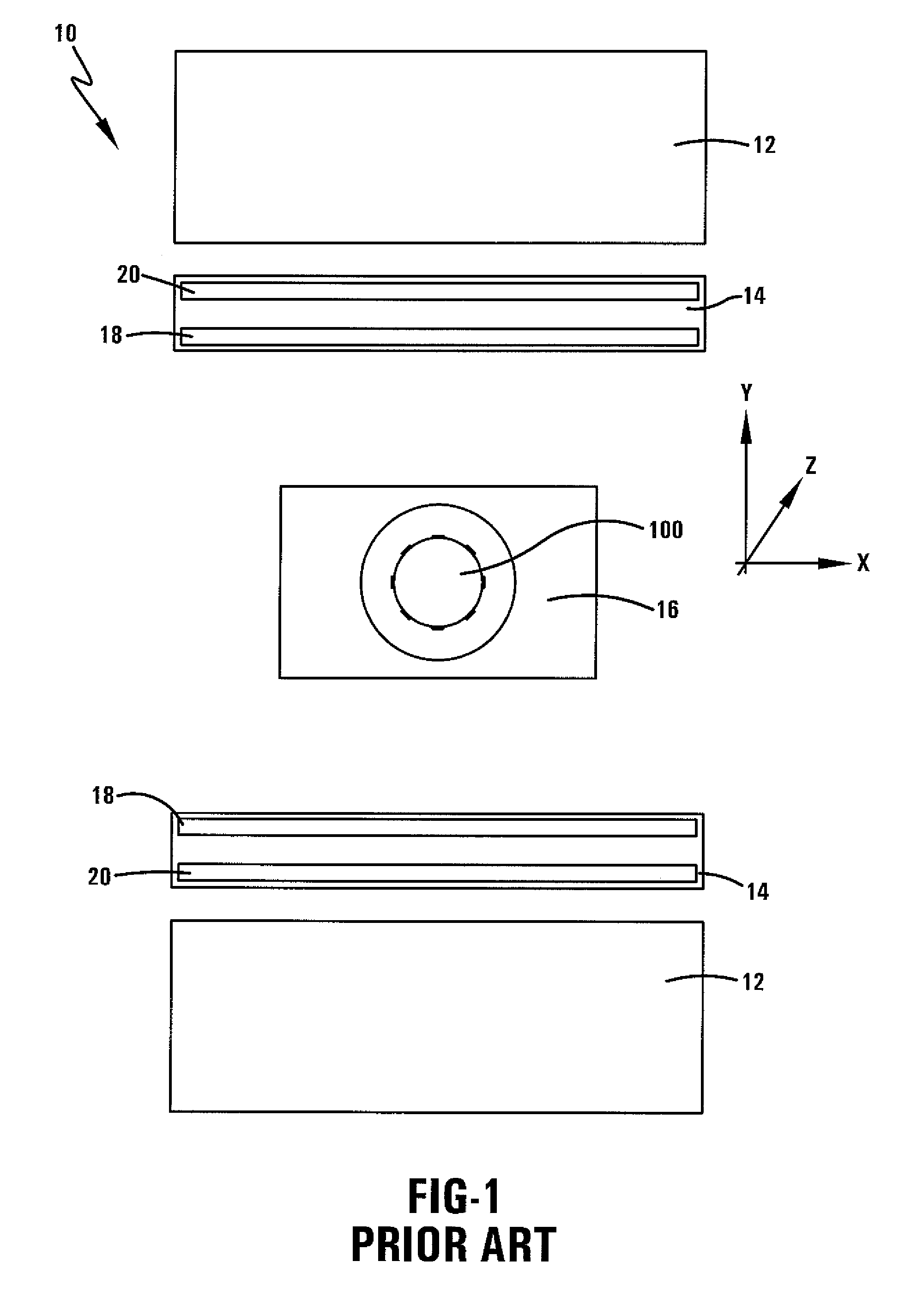
[0034] Referring now to the drawings wherein the showings are for purposes of illustrating numerous embodiments of the invention only and not for purposes of limiting the same, the figures illustrate the novel idea of adding coil booster packs in unused space within the gradient coils and / or within the unused space between the gradient coils and RF coils for the purpose of increasing the homogeneity of the superconducting main magnet of the magnetic resonance imaging (MRI) system.

[0035] This invention is applicable to any superconducting magnet system, including horizontal field magnets, vertical field magnets, and any other type of magnet system. This invention will commonly be used with a superconducting magnet system used in an MRI system, including but not limited to a horizontal field closed system, a vertical field open system, or any other type of magnet of any strength. In the center of system 10 in FIG. 2 is an imaging volume of interest 100. Non-limiting examples of an im...


PUM


Abstract

Described herein is a magnet system for use in imaging a volume that includes a main magnet and at least one magnet coil assembly positioned between the main magnet and the imaging volume. A gradient coil assembly including an inner primary gradient coil alone or with the addition of an outer secondary gradient coil may also exist between the main magnet and imaging volume. The magnet coil assembly may then be positioned between the inner primary gradient coil and the imaging volume, between the inner primary gradient coil and outer secondary gradient coil, or in both positions. Also described herein is an MRI system incorporating the magnet system with additional magnet coil assemblies, and the process for improving the homogeneity of a magnet system using the additional magnet coil assemblies.

Description

TECHNICAL FIELD [0001] The invention relates generally to a magnet system for a magnetic resonance imaging (MRI) system. More specifically, this invention relates to a magnet system with booster coils for improved field homogeneity for a magnet system. BACKGROUND OF THE INVENTION [0002] Magnetic resonance imaging (MRI) is a medical diagnostic imaging technique used to diagnose many types of injuries and medical conditions. An MRI system includes a main magnet for generating a main magnetic field through an examination region. The main magnet is arranged such that its geometry defines the examination region. The main magnetic field causes the magnetic moments of a small majority of the various nuclei within the body to be aligned in a parallel or anti-parallel arrangement. The aligned magnetic moments rotate around the equilibrium axis with a frequency that is characteristic for the nuclei to be imaged. An external radiofrequency (RF) field applied by other hardware within the MRI sy...

Claims


Application Information

Patent Timeline
Patent Type & Authority Applications(United States)
IPC IPC(8): G01V3/00
CPCG01R33/3815G01R33/3875G01R33/3873
Inventor PETROPOULOS, LABROS S.STECKNER, MICHAEL
Owner HITACHI MEDICAL SYSTEMS AMERICA INC
Learn More