
Three-phase harmonic reduction filter for bidirectional power converters

a filter and harmonic reduction technology, applied in the direction of harmonic/ripple reduction dc circuit, overvoltage protection resistor, emergency protective arrangement for limiting excess voltage/current, etc., can solve the problem of reducing the reliability of power distribution equipment, increasing the voltage level of total harmonic distortion, and reducing the electromagnetic compatibility of loads

Active Publication Date: 2007-11-15
MTE CORP
View PDF24 Cites 11 Cited by
  • Summary
  • Abstract
  • Description
  • Claims
  • Application Information

AI Technical Summary

Benefits of technology

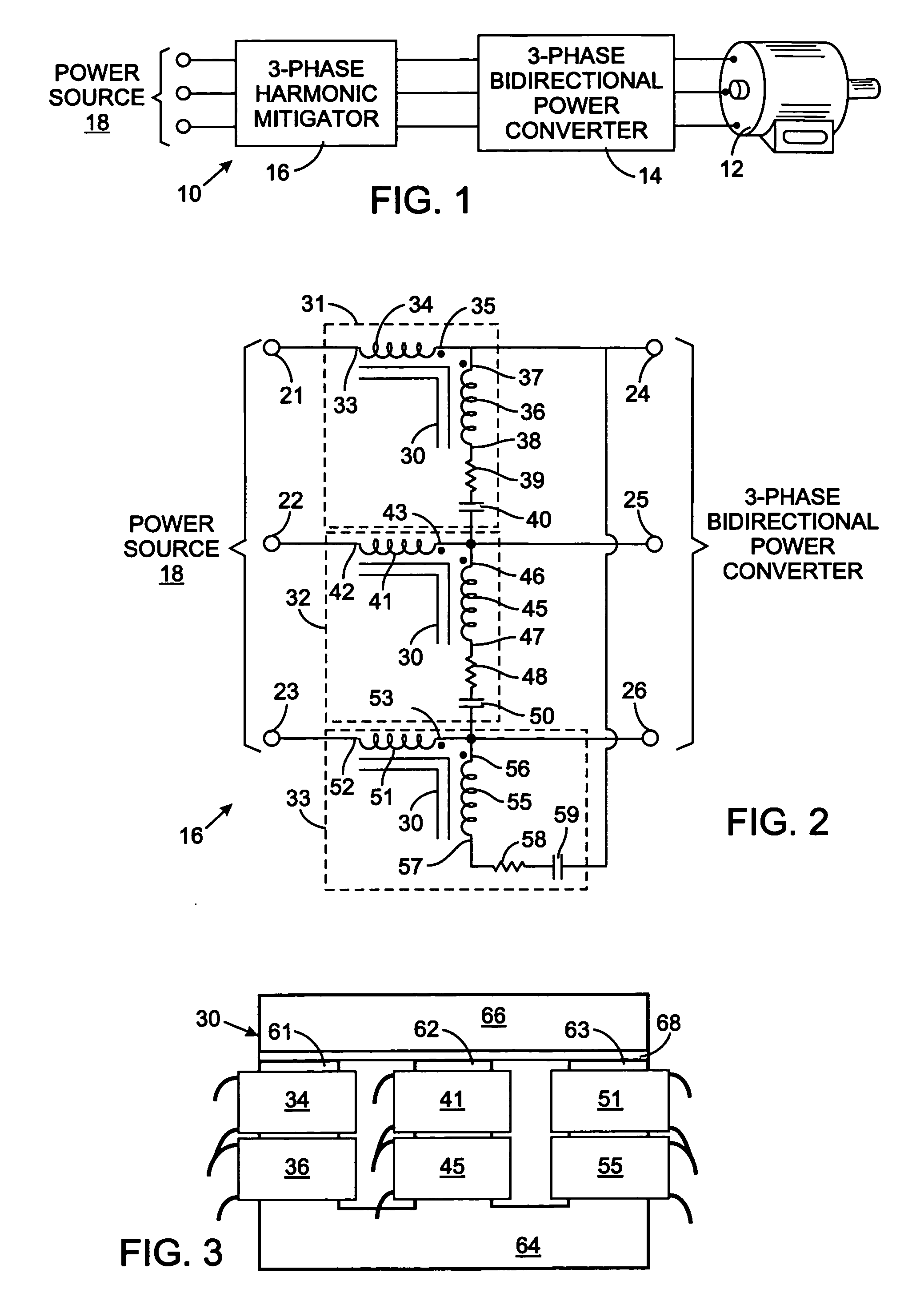
[0013] The line and shunt windings of each phase filter are magnetically coupled in a manner that lessens the total reactance between the power source connector and the load connector for the associated electrical phase line. That coupling also provides a low impedance shunt path back to the load for high frequency harmonics in the regenerative mode of operation, while also providing sufficient phase line impedance for harmonic currents from the power source in the motoring mode of operation.

Problems solved by technology

The harmonic currents create many problems in the power distribution system, including increased total harmonic distortion voltage level, reduced power distribution equipment reliability, reduced electromagnetic compatibility of the loads, increased power losses, reduced power factor, and other problems which are well known to those skilled in the art.
However, conventional filters added an undesirable amount of reactance between the supply lines and the load.

Method used


Image

  • Three-phase harmonic reduction filter for bidirectional power converters
  • Three-phase harmonic reduction filter for bidirectional power converters
  • Three-phase harmonic reduction filter for bidirectional power converters

Examples


Embodiment Construction

[0019] With initial reference to FIG. 1, a circuit 10 for controlling application of electricity to a load, such as a three-phase motor 12 includes a conventional bidirectional power converter 14. A three-phase filter 16 is provided to mitigate harmonic currents that otherwise flow between the three phase lines of power source 18 and the power converter 14.

[0020] With additional reference to FIG. 2, the three-phase filter 16 has first, second and third power source connectors 21, 22 and 23, respectively, to which the three lines of power source 18 are connected. The filter 16 also has first, second and third load connectors 24, 25 and 26 connected to the input terminals of the bidirectional power converter 14. The power source connectors and the load connectors may be terminals to which wires can be attached or they simply may be electrical leads extending from electrical windings of the filter that will be described.

[0021] A separate phase filter 31, 32 or 33 is connected between...


PUM


Abstract

A three-phase filter has first, second, and third power source connectors and first, second, and third load connectors. A separate phase line filter is connected between each pair of power source and load connectors. Each phase line filter includes a line winding connected between the power source and load connectors for a phase line and includes a first shunt winding, resistor and capacitor connected in series between that load connector and the load connector for another phase line. The line and shunt windings for a given phase line filter are wound on a core in directions so that one winding produces magnetic flux having an opposite polarity to the magnetic flux produced by the other winding. The magnetic coupling of those windings, mitigates harmonic currents that otherwise flow in either direction between the power source and load connectors.

Description

CROSS-REFERENCE TO RELATED APPLICATION [0001] Not Applicable STATEMENT REGARDING FEDERALLY SPONSORED RESEARCH OR DEVELOPMENT [0002] Not Applicable BACKGROUND OF THE INVENTION [0003] 1. Field of the Invention [0004] The present invention relates to electrical power distribution systems, and more particularly to filters for mitigating harmonic currents in such systems. [0005] 2. Description of the Related Art [0006] Electrical loads are commonly controlled by power converters, such as adjustable speed drives for operating large electric motors, which convert AC power at one frequency to another frequency. Power converters for electric motors often are bidirectional so that when the motor is being driven by the mechanical load in a regenerative mode, the motor acts as a generator sending electrical current back through the power converter into the utility lines. [0007] Non-linear electrical loads produce various levels of harmonic currents in the power distribution system with the harm...

Claims


Application Information

Patent Timeline
IPC IPC(8): H02H3/22
CPCH02M1/126
Inventor SHUDAREK, TODD A.
Owner MTE CORP
Learn More