

Optical flip-flop circuit
a flip-flop circuit and flip-flop technology, applied in the direction of generating/distributing signals, pulse techniques, instruments, etc., can solve the problems of structural structure of optical flip-flop circuits and the necessity of raising the cost of manufacturing optical flip-flop circuits
- Summary
- Abstract
- Description
- Claims
- Application Information
AI Technical Summary
Problems solved by technology
Method used
Image

Examples
Embodiment Construction
[0016] The present invention has the above characteristics. Embodiments of the present invention will be explained below.
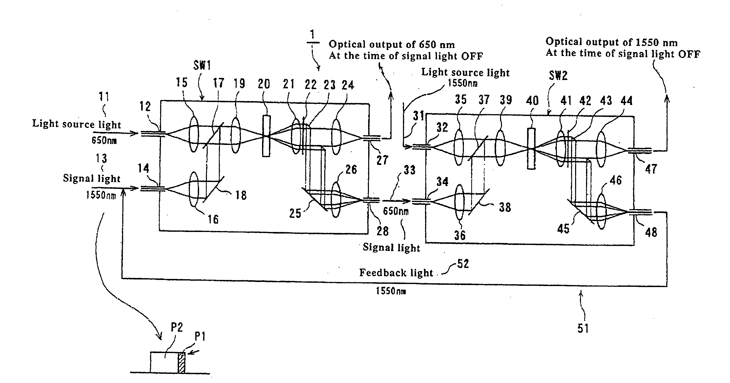
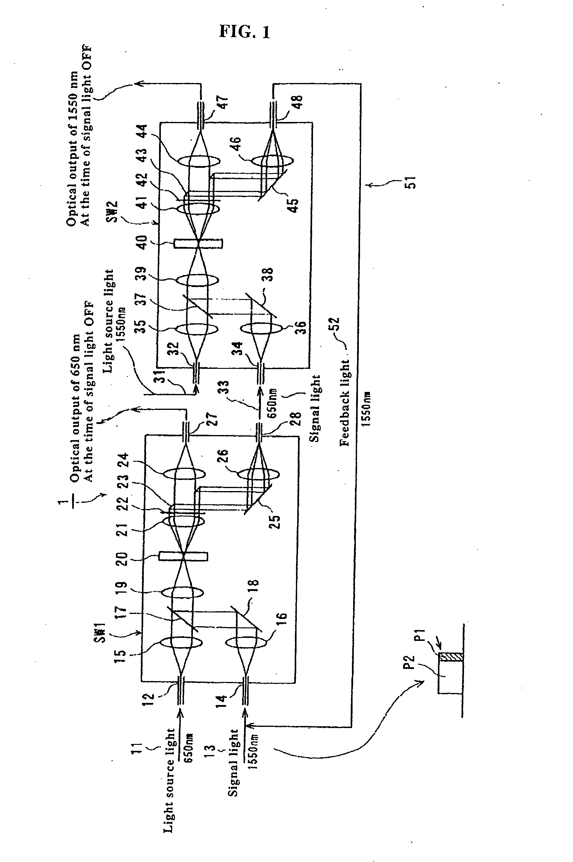
[0017]FIG. 1 is a schematic illustration showing a structure of an optical flip-flop circuit of an embodiment of the present invention.
[0018] In this optical flip-flop circuit (1), a first switch (SW1) and a second switch (SW2) are arranged in series to each other.
[0019] The first switch (SW1) includes: an input port (12) for taking in light source light (11) which is continuous light (CW), the wave-length of which is 650 nm; and an input port (14) for taking in pulse-shaped signal light (gate light) (13), the wave-length of which is 1550 nm. On the downstream side of the input port (12), a lens (15) is arranged which makes light source light (11), which has been incident, to be parallel light. On the downstream side of the input port (14), a lens (16) is arranged which makes signal light (13), which has been incident, to be parallel light. On the downstream si...
PUM
 Abstract
Description
Claims
Application Information