Stand-alone low noise amplifier

a low-noise amplifier and stand-alone technology, which is applied in the direction of digital transmission, electrical apparatus, radio transmission, etc., can solve the problems of reducing the reliability of such systems, reducing the length of the loop around the lna system, and reducing the cost and maintenance burden. , to achieve the effect of reducing the loop gain, reducing the inband ripple, and increasing the loop length

Active Publication Date: 2007-11-15
APPLE INC
View PDF11 Cites 13 Cited by
  • Summary
  • Abstract
  • Description
  • Claims
  • Application Information

AI Technical Summary

Benefits of technology

[0009]The use of circulators in the LNA system overcomes the need for transmit / receive switches. The LNA system has minimal attenuation during a transmit burst and the low noise amplifier in the receive path provides gain during the receive burst. The LNA system is completely stand-alone and operates independently of the base station. As the LNA system does not require a control from the base station this avoids the need to provide a standardized control interface between the transceiver system and the LNA system or to make any modification to the transceiver system. The limiter device in the receive path ensures that a high level of attenuation is applied to the receive path when the input signal exceeds a predetermined level, such as can occur when transmitted power leaks from the transmit path, through the second circulator, and into the receive path during a transmit phase of the TDD signal.
[0011]Interconnecting the first circulator of each sub-unit with the second circulator of another sub-unit has the effect of increasing the length of the loop around the LNA system. This reduces the loop gain and minimises inband ripple.

Problems solved by technology

Furthermore, it is difficult to realize a Tx / Rx switch 21 which can switch at high power and with low loss.
This implies a high cost as well as some additional leasing and maintenance burden, and decreases the reliability of such systems.

Method used


Image

  • Stand-alone low noise amplifier
  • Stand-alone low noise amplifier
  • Stand-alone low noise amplifier

Examples


Embodiment Construction

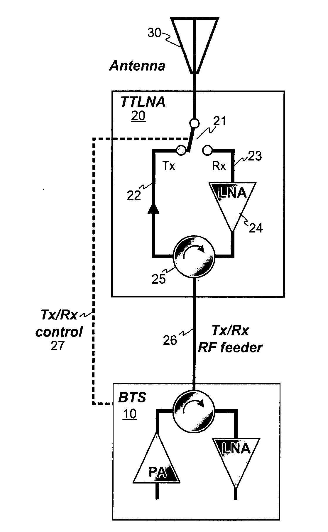
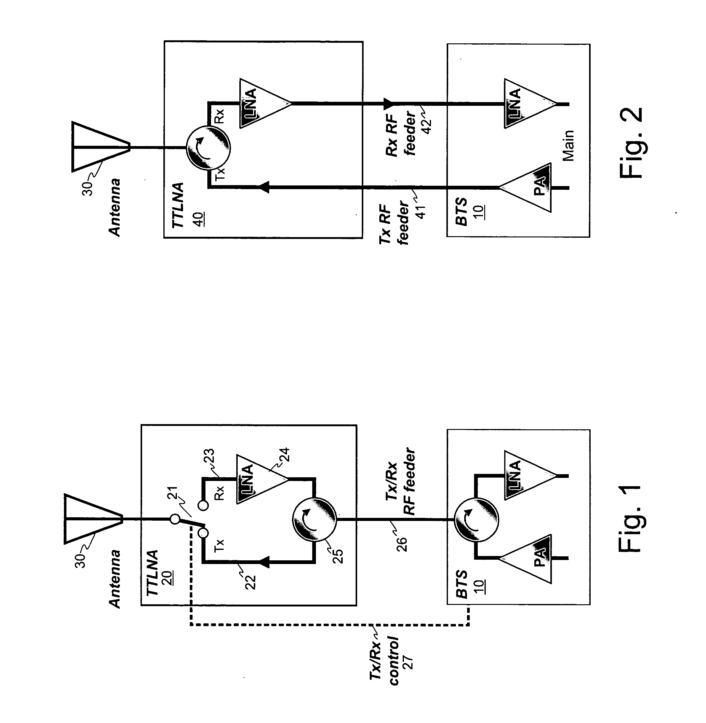
[0023]The present invention provides Low Noise Amplifier (LNA) systems particularly well suited for Time Division Duplex (TDD) wireless access networks, such as WIMAX or UMTS TDD access networks.

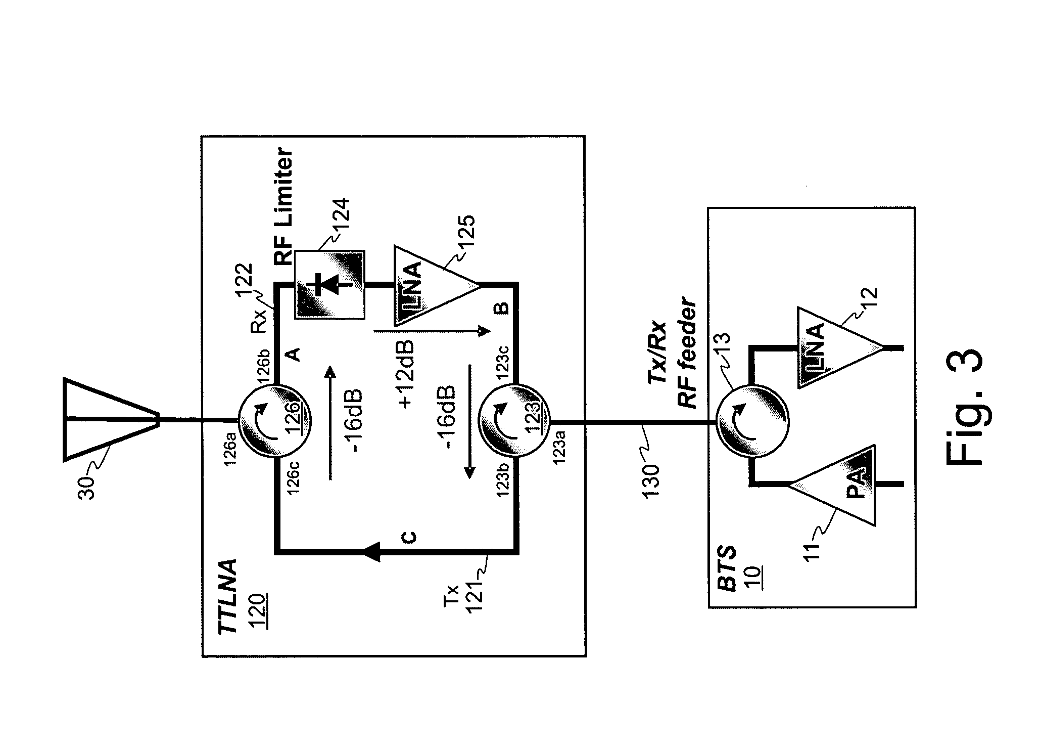
[0024]FIG. 3 shows a first embodiment of an improved LNA system in accordance with the invention. The improved LNA system 120 comprises two circulators 123, 126. A first circulator 123 connects a single Tx / Rx RF feeder cable 130 from the base station 10 to the LNA system 120. A second circulator 126 connects the LNA system 120 to the antenna 30. In this embodiment each circulator 123, 126 is a device having three ports. Power applied to a port is output from the next port, when viewed in the direction shown by the arrow on the circulator. Looking at circulator 123, a first port 123a is connected to the Tx / Rx RF feeder 130 which connects the base station to the LNA system, the second port 123b connects to the transmit path 121 and the third port 123c connects to the output of the receive path...


PUM


Abstract

A time division duplex (TDD) wireless apparatus includes a low noise amplifier (LNA) system, at least one antenna and a transceiver system. The apparatus supports N time division duplexed channels which each have a transmit direction of transmission flow and a receive direction of transmission flow. The LNA system comprises N sub-units. Each sub-unit comprises a first circulator for connecting to a respective TX / RX feed to the transceiver system and a second circulator for connecting to the at least one antenna. The first circulator and second circulator within each sub-unit are interconnected to provide a path in one of the directions of transmission flow. The first circulator of each sub-unit is connected to the second circulator of another sub-unit to provide a path in the other direction of transmission flow. A single channel variant is also provided.

Description

CROSS-REFERENCE TO RELATED APPLICATION[0001]This claims the benefit under 35 U.S.C. § 119(e) of U.S. Provisional Application Ser. No. 60 / 799,084, filed May 10, 2006, which is hereby incorporated by reference.FIELD OF THE INVENTION[0002]The present invention relates to low noise amplifiers (LNA) used in wireless systems. It is in particular directed to low noise amplifiers used in Time Division Duplex (TDD) wireless systems.BACKGROUND OF THE INVENTION[0003]Low Noise Amplifier (LNA) systems are provided as part of base stations in wireless access networks and are typically positioned between the Base Transceiver System (BTS) of a base station and an antenna. Typically, the LNA system is positioned close to the antenna, at the top of an antenna mast or other supporting structure, and is called a Tower Mount Amplifier (TMA) or a Tower Top LNA (TTLNA). The main purpose of the LNA system is to amplify a received signal before forwarding the signal to a receiver in the BTS where the signal...

Claims


Application Information

Patent Timeline
IPC IPC(8): H04B7/185H04B1/18H04B1/16
CPCH04B1/52H04B1/18
Inventor HOLDER, PHILIPDOLMAN, GRAHAM
Owner APPLE INC
Why Eureka
Try Eureka