
Multithreaded computer system and multithread execution control method

Active Publication Date: 2007-11-15
BEIJING ESWIN COMPUTING TECH CO LTD
View PDF51 Cites 73 Cited by
  • Summary
  • Abstract
  • Description
  • Claims
  • Application Information

AI Technical Summary

Benefits of technology

[0014]In view of the above problems, the present invention has an object to provide a multithreaded computer system and a multithread execution control method that are capable of enhancing substantial availability of plural processor elements.
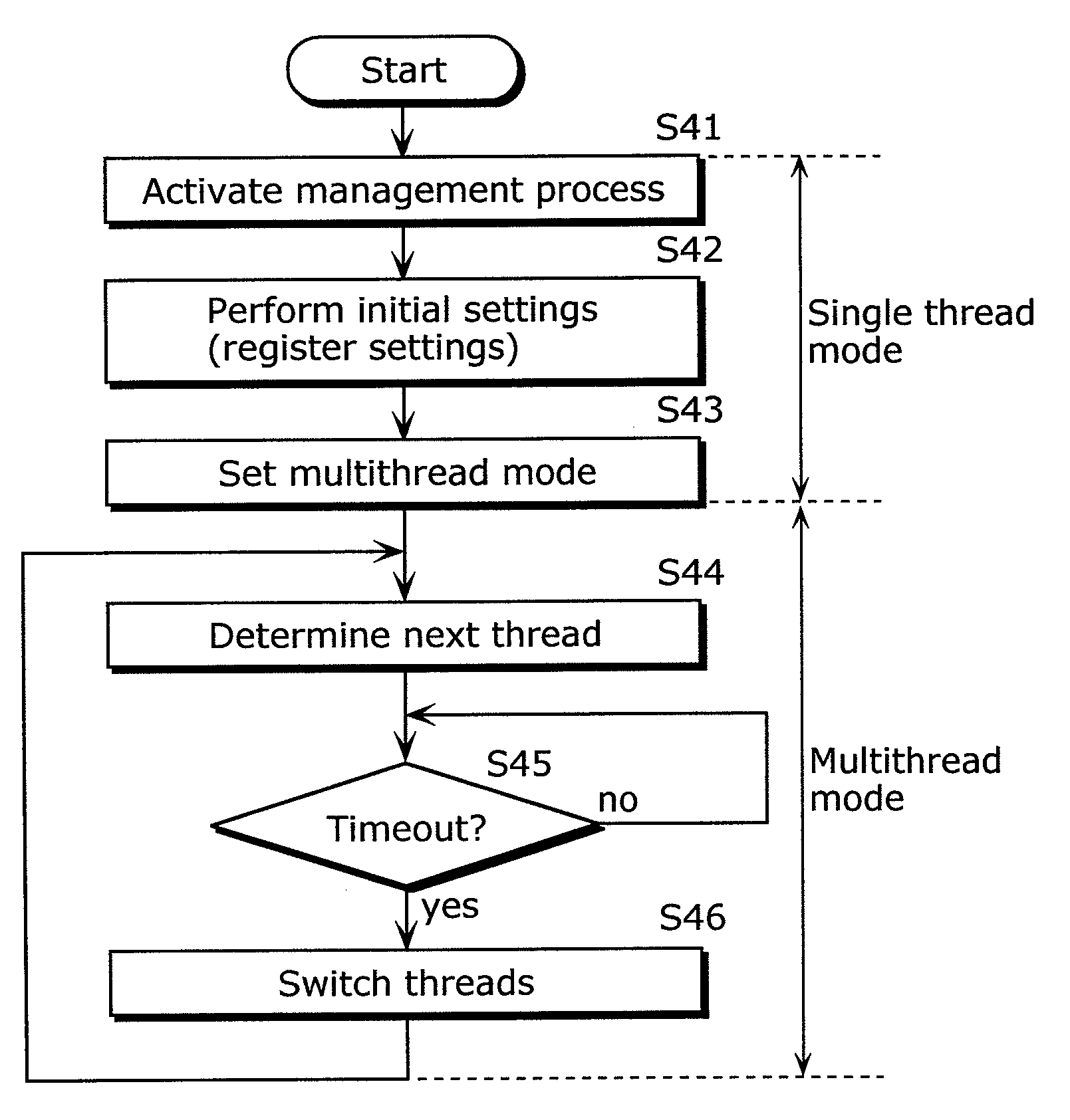
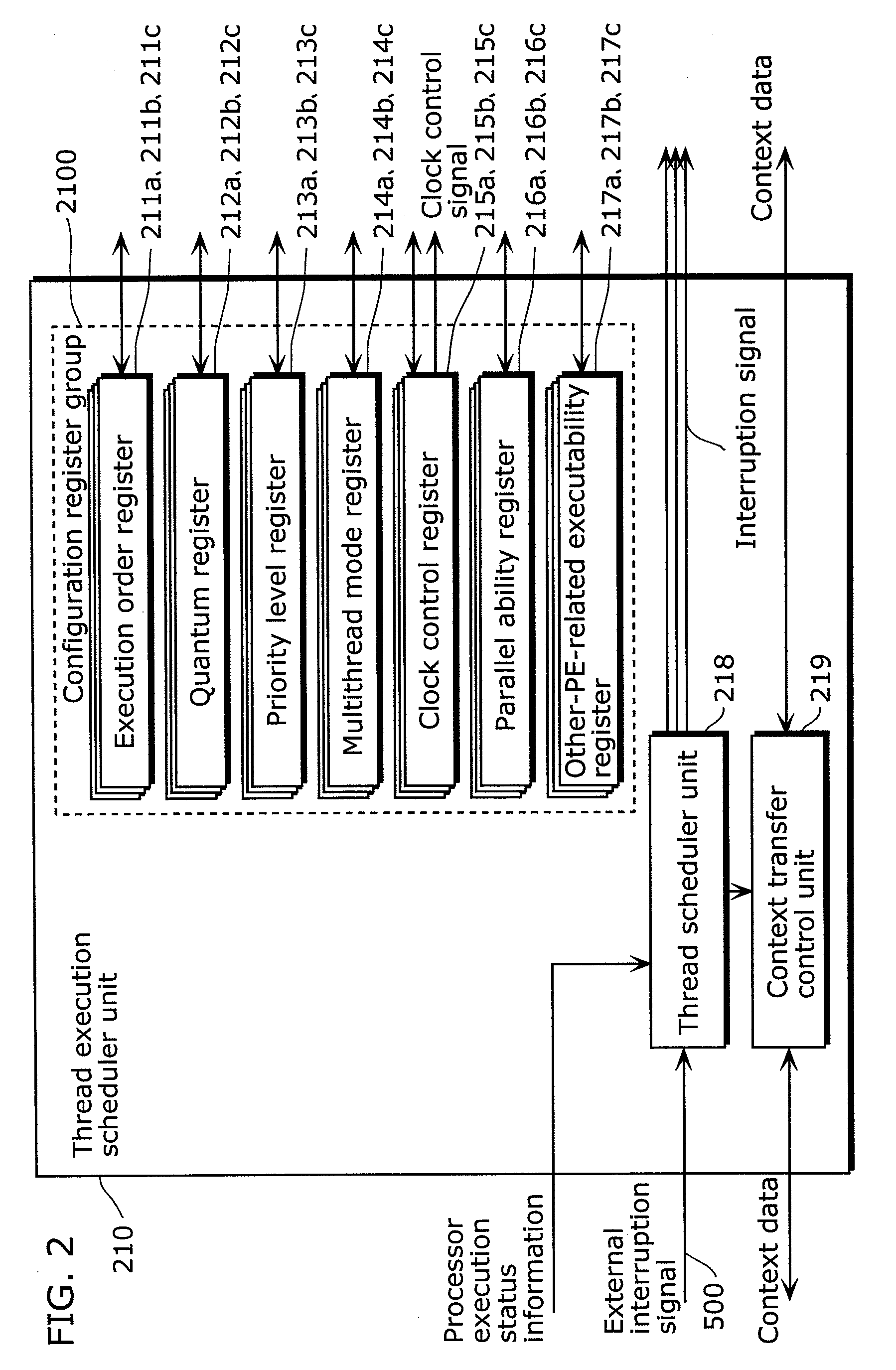
[0015]In order to achieve the above object, a multithreaded computer system includes: a plurality of processor elements, each of which executes a process including a plurality of threads; and a control unit which switches threads to be executed in each processor element, in which the control unit includes: a plurality of execution order registers, each of which is provided for a corresponding one of the processor elements, and which holds an execution order of threads to be executed by the corresponding processor elements; a plurality of counters, each of which is provided for a corresponding one of the processor elements, each counter counting an execution time period for a thread that is being executed by the corresponding processor element and generating a timeout signal when the counted time reaches a limit assigned to the thread; and a scheduling circuit operable to switch the thread that is being executed to the thread to be executed by each processor element based on the execution order held in said execution order register and the timeout signal. With this configuration, determination of the next thread to be executed and thread switching are performed by the scheduling circuit, making it possible to reduce thread switching overhead, so that the substantial availability of the multithreaded computer system can be enhanced.
[0019]In addition, each of the processor elements may include two context register groups which hold a context for a thread that is being executed and a context for a thread that is to be executed next, the scheduling circuit may further include a context transfer unit operable to transfer context to save and restore contexts for the processor elements, the scheduling circuit may switch the context register groups at the time of thread switching, and the context transfer unit may transfer the context after the thread switching. With this configuration, saving and restoring of contexts can be hidden, making it possible to further enhance the availability of the multithreaded computer system.
[0020]In addition, the control unit may further include: a status register indicating whether each processor element is in an execution state or in a stopped state; and a plurality of possibility information holding units provided corresponding to the processor elements, each possibility information holding unit holding possibility information as to whether parallel thread execution is possible, and when any of the processor elements has transitioned from the execution state to the stopped state, the scheduling circuit may further determine a thread available for parallel execution from among threads for other processor elements based on the possibility information, and cause the processor element in the stopped state to execute the determined thread. With this configuration, the processor element in the stopped state can be efficiently utilized to cause one process to be executed not only by a single processor element but also by a plurality of processor elements, whereby it is possible to further enhance the availability of the multithreaded computer system.
[0023]In addition, the control unit may further include a clock control register which holds clock control information indicating whether or not clock supply should be suppressed, for each processor element, and the control unit may enable or disable the clock control unit for each processor element in accordance with the clock control information. With this configuration, it is possible to suppress clock supply to processor elements in the stopped state for each processor element.
[0025]As is apparent from the above description, the present invention makes it possible to significantly reduce time loss in thread switching in a parallel processing system for executing fine grain threads, while switching the threads. In addition, it is possible to efficiently utilize processor elements in the stopped state. Thus, it is possible to enhance the availability of the multithreaded computer system.FURTHER INFORMATION ABOUT TECHNICAL BACKGROUND TO THIS APPLICATION

Problems solved by technology

However, the conventional technology has the following problems.
Specifically, the first problem of the conventional technology is such that every time the threads are switched, thread switching overhead occurs.
The second problem of the conventional technology is such that even when plural threads in a single user process can be executed in parallel, a single processor element is assigned to the single user process, and thus even if another processor element is not executing any thread in another user process, it is not possible to cause that processor element to execute any thread in the same process.
Therefore, it is not possible to satisfactorily enhance substantial availability of the parallel processing system, leading to a reduction in system performance.

Method used


Image

  • Multithreaded computer system and multithread execution control method
  • Multithreaded computer system and multithread execution control method
  • Multithreaded computer system and multithread execution control method

Examples


Embodiment Construction

[0033]Hereinafter, an embodiment of the present invention will be described in detail with reference to the drawings.

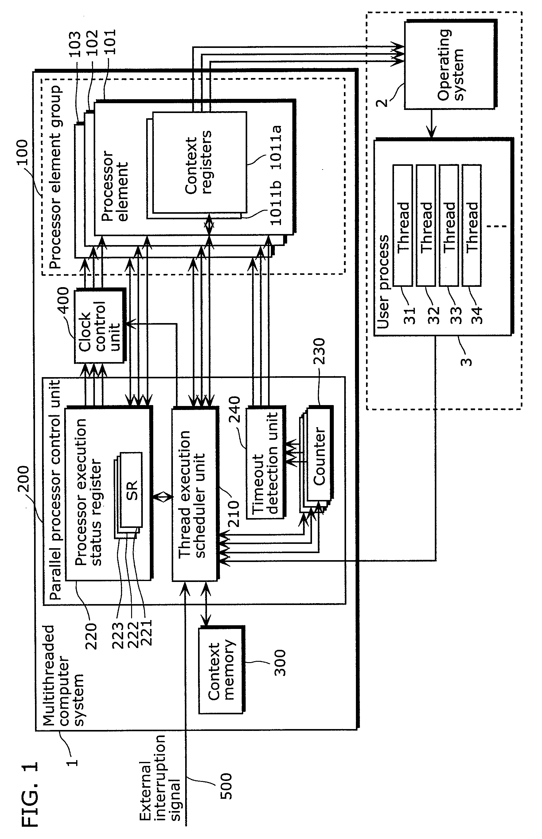
[0034]FIG. 1 is a functional block diagram illustrating the overall configuration of a multithreaded computer system according to an embodiment of the present invention.

[0035]As shown in FIG. 1, a multithreaded computer system 1 includes a processor element group 100, a parallel processor control unit 200, a context memory 300, and a clock control unit 400. Note that schematically shown within broken lines at the bottom of the diagram are an operating system 2 and a user process 3 that are stored in memory.

[0036]The processor element group 100 includes plural processor elements. For ease of explanation, the processor element group 100 herein includes three processor elements: a first processor element 101, a second processor element 102 and a third processor element 103. Each processor element executes a thread in a process including plural threads, while switching th...


PUM


Abstract

A multithreaded computer system of the present invention includes a plurality of processor elements (PEs) 101 to 103, and a parallel processor control unit 200, which switches threads in each PE, and the parallel processor control unit 200 includes: a plurality of execution order registers, which hold, for each processor element, an execution order of threads to be executed; a plurality of counters 230, which count an execution time for a thread that is being executed by each processor element and generate a timeout signal when the counted time reaches a limit assigned to the thread; and a thread execution scheduler unit 210, which switches the thread that is being executed to the thread to be executed by each processor element based on the execution order held in said execution order register and the timeout signal.

Description

BACKGROUND OF THE INVENTION[0001](1) Field of the Invention[0002]The present invention relates to multithreaded computer systems including multiprocessor elements that operate in parallel, and particularly to a multithreaded computer system and a multithread execution control method that switch programs in each processor element.[0003](2) Description of the Related Art[0004]There are parallel processing systems that have a multiprocessing architecture including plural processor elements in order to provide an enhanced processing capability.[0005]In some cases, in order to further enhance the processing capability, the parallel processing systems employ a method in which one process is divided into plural control flows (programs) called “threads”, and the threads are executed in parallel by plural processors.[0006]For example, Japanese Laid-Open Patent Publication No. 11-282815 discloses a conventional method for use with a parallel processing system that have a multiprocessing archi...

Claims


Application Information

Patent Timeline
IPC IPC(8): G06F9/46
CPCY02B60/144G06F9/4843Y02D10/00
Inventor HENMI, MASANORI
Owner BEIJING ESWIN COMPUTING TECH CO LTD
Learn More