Non-contact ultrasonic testing method and device for ceramic honeycomb structures

Active Publication Date: 2007-11-22
CORNING INC
View PDF22 Cites 20 Cited by
  • Summary
  • Abstract
  • Description
  • Claims
  • Application Information

AI Technical Summary

Benefits of technology

[0012] The ultrasonic transmitter and receiver may be positioned in a non-contact position closely adjacent to the outer walls of the structure. After the first filtered response signal has been analyzed, the ultrasonic transmitter and receiver are re-located relative to the honeycomb structure and actuated again so that any internal discontinuities or inhomogeneities are ultimately detected. In lieu of sequential relocation of a single ultrasonic transmitt

Problems solved by technology

Unfortunately, during the extrusion, handling and firing procedures, internal damage can occur within the ceramic substrate which can compromise the performance of the body in removing pollutants from the automotive exhaust system where it ultimately resides.
Still other damage is manifested by a localized separation between the network of web walls, and the outer skin of the structure.
Finally, external hairline cracks on the surface of the structure can occur, or other strength-compromising scratches and deformities.
However, such x-ray inspections are insensitive to the internal crac

Method used


Image

  • Non-contact ultrasonic testing method and device for ceramic honeycomb structures
  • Non-contact ultrasonic testing method and device for ceramic honeycomb structures
  • Non-contact ultrasonic testing method and device for ceramic honeycomb structures

Examples


Embodiment Construction

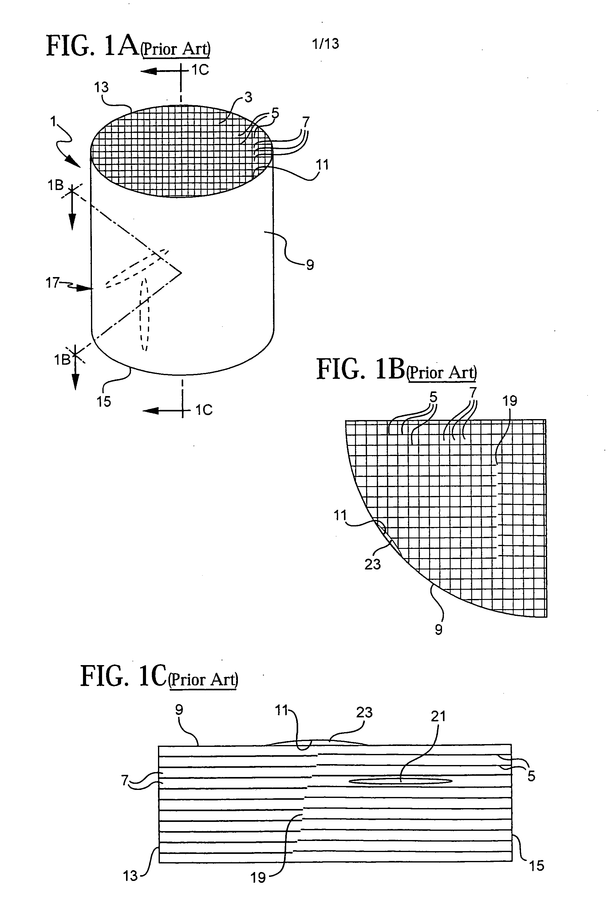
[0035] With reference now to FIGS. 1A, 1B and 1C, both the method and the device of the invention are particularly useful in detecting discontinuities and other inhomogenieties which may be present in a ceramic honeycomb structure 1 of the type used in diesel and automotive exhaust systems. Such structures include a network 3 of web walls 5 that define gas-conducting cells 7 along the axis of rotation of the structure 1. The network 3 of web walls 5 is surrounded by an outer skin 9. The outer skin 9 has an inner edge 11 that is generally integrally connected (except, for example, at defects) to the outer edges of the network 3 of walls 5, as is best seen in FIG. 1B. The resulting can-shaped structure has an inlet end 13 for receiving exhaust gases from a diesel engine or automobile engine, and an outlet end 15 for expelling these gases.

[0036] Ceramic honeycomb structures 1 used as flow-through catalyst substrates have cells 7 which are completely open between the inlet and outlet e...


PUM


Abstract

Both a method and apparatus for determining internal discontinuities or inhomogeneities in a green or fired ceramic honeycomb structure is provided. In the method of the invention, an ultrasonic transmitter is positioned adjacent to, but not in contact with, the honeycomb structure. The transmitter propagates an ultrasonic wave, of preferably less than 5 MHz, through the honeycomb structure which is received, filtered and analyzed to determine the presence or absence of internal discontinuities or inhomogenieties. The ultrasonic transmitter generates an ultrasonic wave of less than five megahertz to provide a relatively high signal-to-noise ratio in the ultrasonic wave propagated through the structure. The device of the invention may include an array of ultrasonic transmitters and receivers that generate simultaneously transmit and receive ultrasonic signals throughout the ceramic honeycomb structure as it is moved relative to the array such that the structure is quickly and efficiently scanned for discontinuities or inhomogenieties.

Description

FIELD OF THE INVENTION [0001] This invention generally relates to methods for detecting internal defects in ceramic honeycomb structures, and is specifically concerned with an ultrasonic testing method and device that quickly and efficiently determines presence or absence of internal defects within such structures. BACKGROUND OF THE INVENTION [0002] Ceramic honeycomb structures are used in vehicular exhaust systems to reduce pollutants. Such structures generally comprise a network of interconnected web walls that form a matrix of elongated, gas-conducting cells which may be square, octagonal or hexagonal in shape, for example. The network of web walls is surrounded by a cylindrical outer skin that is integrally connected to the outer edges of the web walls to form a can-or oval-shaped structure having opposing inlet and outlet ends for receiving and expelling exhaust gases through the matrix of cells. [0003] Such ceramic honeycomb structures may be used as either particulate filters...

Claims


Application Information

Patent Timeline
IPC IPC(8): G01N9/04
CPCG01N29/11G01N29/27G01N2291/106G01N2291/0231G01N2291/0232G01N29/348
Inventor HAMPTON, LESLIE EUGENESHI, ZHIQIANG
Owner CORNING INC
Why Eureka
Try Eureka