Clutch arrangement

a technology of clutches and cylinders, applied in the direction of fluid actuated clutches, non-mechanical actuated clutches, clutches, etc., can solve the problems of poor control accuracy of gearboxes, shortened corresponding supply lines, and shortened length of corresponding supply lines, so as to reduce the complexity of the layout of the lines through which fluid is guided, and the effect of high pressur

Inactive Publication Date: 2007-11-22
ZF FRIEDRICHSHAFEN AG
View PDF7 Cites 11 Cited by
  • Summary
  • Abstract
  • Description
  • Claims
  • Application Information

AI Technical Summary

Benefits of technology

[0013]Insofar as the supply unit, especially in this case the supply source, as well as the actuating line are provided on the side of the clutch arrangement facing the gearbox, it is advantageous for the pressure space, which is to be actuated in comparably short periods of time with relatively high pressures under open-loop and/or closed-loop control, to be provided also on the side of the clutch arrangement facing the gearbox. As a result, the length of the corresponding supply line can be decreased, and thus not only the complexity of the layout of the lines through whi

Problems solved by technology

For cost reasons, however, gearboxes acting in this way are used only to a limited extent in motor vehicles, especially in passenger vehicles.
The essential feature but also the essential disadvantage of the two-line systems is that there is always a flow connection for the fluid medium between the pressure space and the cooling space.
It is true that, when the clutch arrangement is engaged, the flow passing through this connection is not as great as that which occurs when the clutch arrangement is disengaged, but nevertheless the accuracy with which the clutch can be controlled is worse and the behavior during the engaging and disengaging processes

Method used


Image

  • Clutch arrangement
  • Clutch arrangement
  • Clutch arrangement

Examples


Embodiment Construction

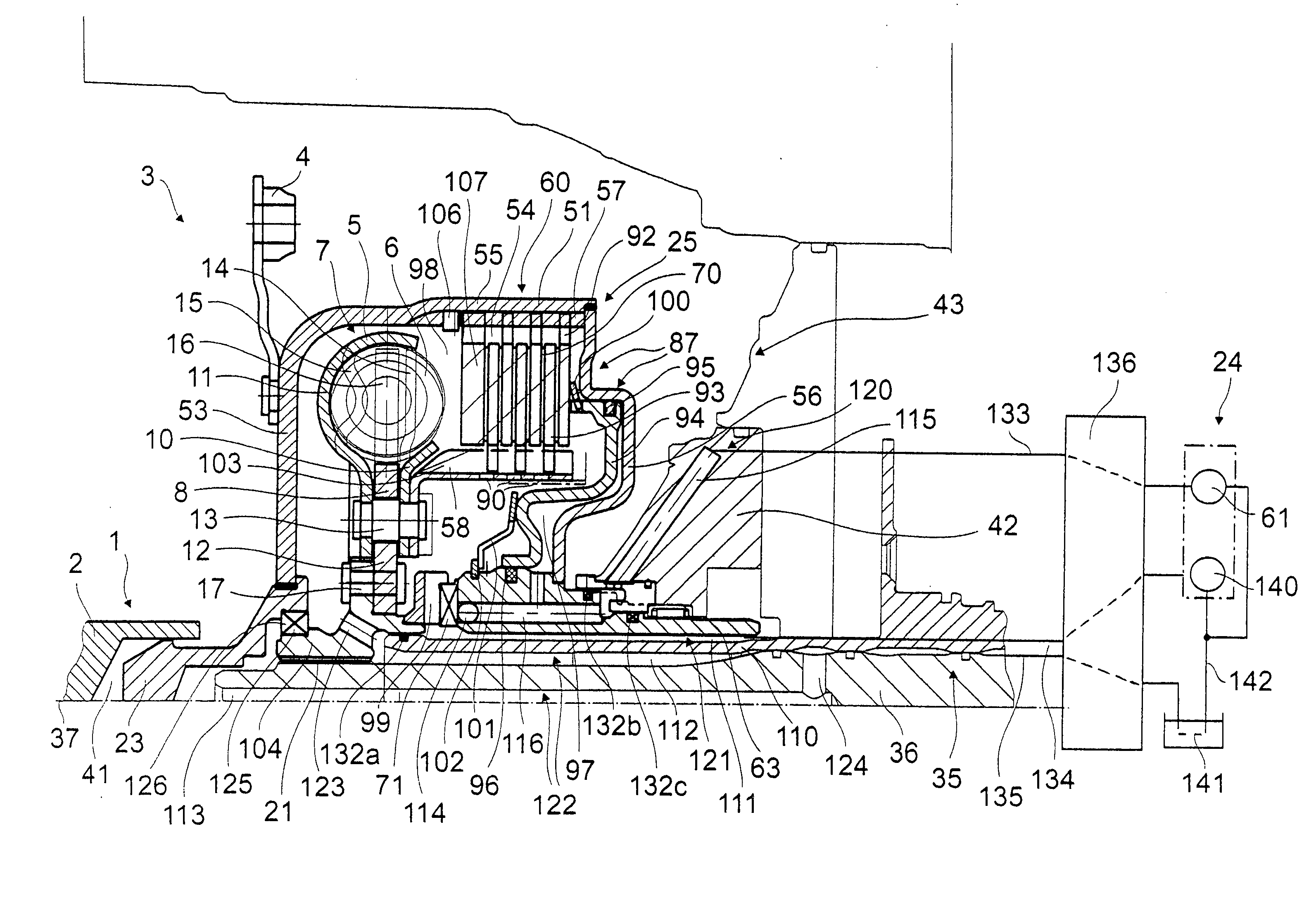
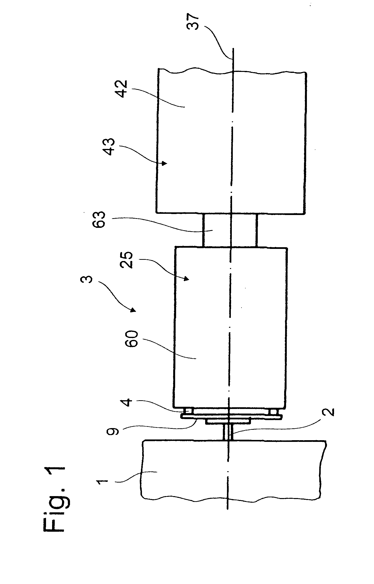
[0017]FIG. 1 shows a schematic diagram of a drive train 3 rotating around an axis of rotation 37 and provided with an inventive clutch arrangement 25. The clutch arrangement 25 includes a clutch housing 60, which can be connected for rotation in common to a drive 1, such as the crankshaft 2 of an internal combustion engine, by means of a plurality of fastening elements 4 and a connecting element 9 such as a flexplate. On the axial side facing away from the drive 1, the clutch housing 60 has a clutch housing hub 63, which engages, for example, in a gearbox 43 and there drives in rotation the supply basis 140, shown only schematically in FIG. 2, of a supply unit 24, where the supply unit 24 can also be designed with a supply source 61. A take-off 35 in the form of a gearbox input shaft 36 is concentric to the clutch housing hub 63. The free end of the shaft projects into the clutch housing 60.

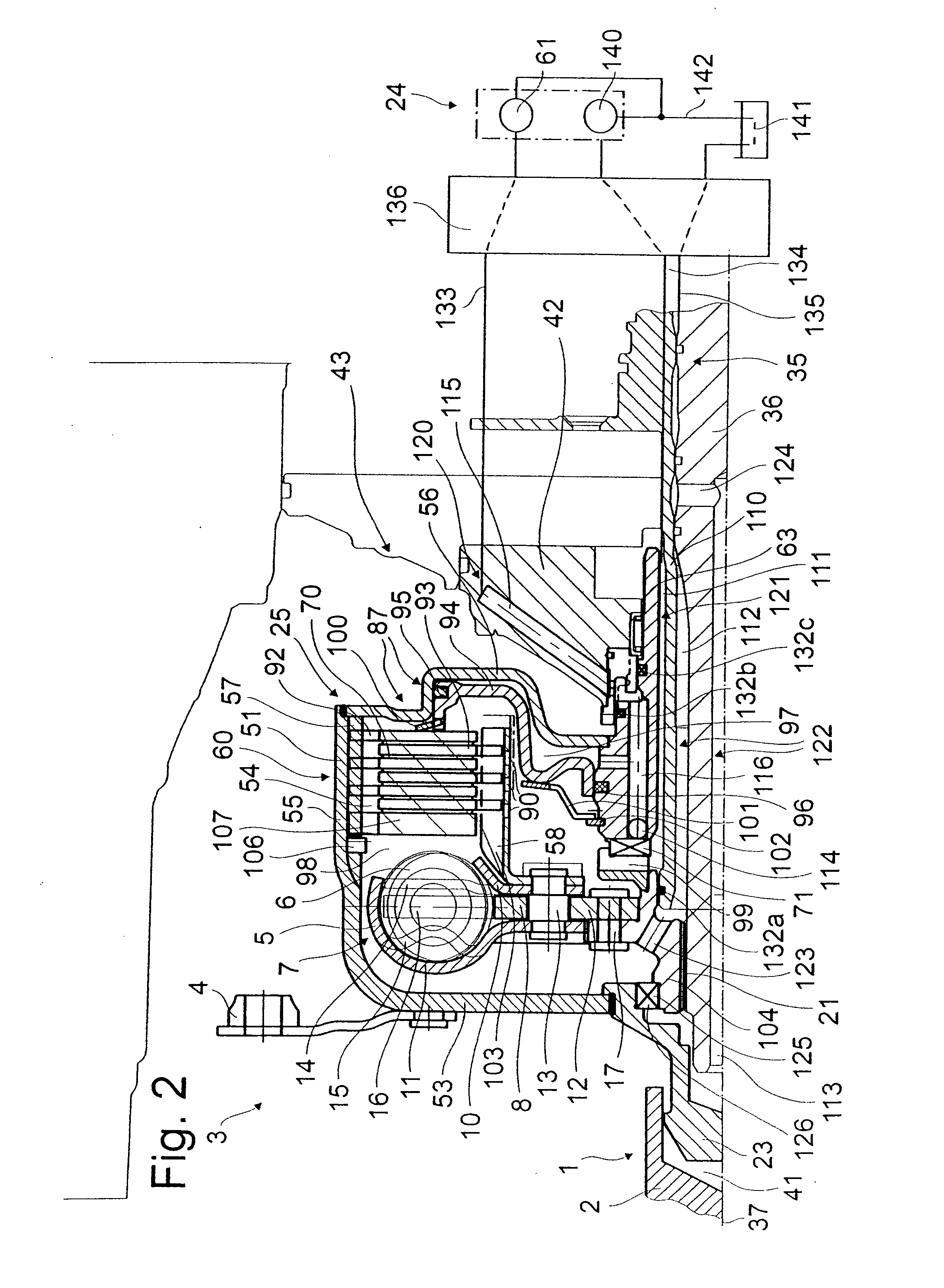
[0018]FIG. 2 shows a bearing journal 23 assigned to the clutch housing 60. The journal engage...


PUM


Abstract

A clutch arrangement has a clutch device with a clutch housing capable of rotating around an axis of rotation, where the clutch device is designed to establish or to separate a working connection between a drive and a take-off and is provided with clutch components in the form of a piston and clutch elements. The piston produces a seal between a pressure space and a cooling space holding the clutch elements. The pressure space or the cooling space is connected to a supply unit so that it can be supplied with fluid medium, by connecting at least one supply line of the clutch device is connected to an infeed line of a gearbox and possibly by connecting at least one discharge line of the clutch device is connected to an outfeed line of the gearbox. An actuating line for a first supply line is assigned to the clutch device. The first supply line is independent of the infeed line for a second supply line or of the outfeed line for a discharge line.

Description

BACKGROUND OF THE INVENTION[0001]1. Field of the Invention[0002]The invention pertains to a clutch arrangement for installation between a drive and a gearbox, the arrangement including a clutch housing which can rotate about an axis of rotation; a clutch including a piston and clutch elements which can be engaged to provide a working connection between the drive and the gearbox, the piston separating a pressure space and a cooling space in which the clutch elements are installed; and a fluid supply unit connected to one of the spaces by a supply line.[0003]2. Description of the Related Art[0004]A clutch arrangement of this type is known from US 2005 / 224308. This clutch arrangement has a clutch device with a clutch housing capable of rotating around an axis of rotation and is used to establish a working connection between a drive such as a crankshaft of an internal combustion engine and a take-off such as a gearbox input shaft when certain clutch components are in the engaged positio...

Claims


Application Information

Patent Timeline
IPC IPC(8): F16D11/00
CPCF16D25/123F16D25/0638
Inventor SUDAU, JORGFENN, PETER
Owner ZF FRIEDRICHSHAFEN AG
Why Eureka
Try Eureka