
Magnetic Tagging

Inactive Publication Date: 2007-11-22
ADVOTEK MEDICAL DEVICES
View PDF14 Cites 3 Cited by
  • Summary
  • Abstract
  • Description
  • Claims
  • Application Information

AI Technical Summary

Benefits of technology

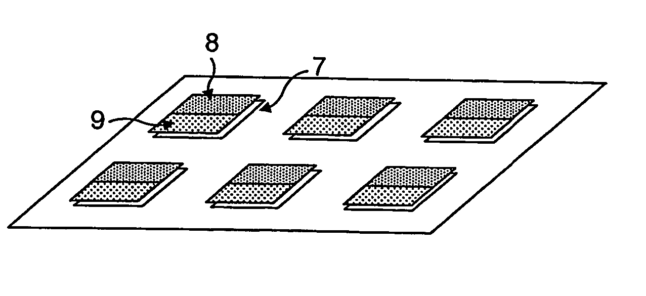
[0011] In a second and alternative aspect of this invention, there is provided an article comprising a magnetic tag or marker adapted to be attached to a selected article to be tagged, and comprising a substrate, preferably flexible, the substrate carrying a spatial distribution of passive magnetic elements, each such magnetic element comprising a layer of soft magnetic material characterised by high permeability, low coercivity and a non-linear B-H characteristic, and formed as a discrete region of such material, and each such magnetic element having associated therewith at least one second layer of magnetic material capable of being permanently magnetised at least in a region adjacent said first layer to provide a magnetic bias for the said magnetic element; the bias of individual said magnetic elements in said spatial distribution and the particular spatial nature of the said distribution for the said tag or marker enabling the article to be tagged to be magnetically encoded.
[0013] The invention also extends to a system comprising at least one article as defined above and a reading assembly therefor, the reading assembly comprising means adapted to apply a magnetic bias signal that varies over time to a said magnetic element and means adapted to detect when the said bias signal approximates the said magnetic bias provided by the second layer, thereby enabling the level of the said magnetic bias to be determined.
[0022] As will become clear from the detailed description hereinbelow, articles and systems in accordance with the various aspects of this invention have a wide variety of applications. These include authentication of the origin of replaceable supplies, confirming correct connection of a material supply, preventing connection errors to a medical delivery system and preventing re-use of single use items. A key feature of tags in accordance with this invention is that they have the ability to be written to even when embodied within an article. This has the significant benefit that units may be coded just prior to use, thus reducing lead times and inventory. Moreover, as explained below, there is effectively no limit to the number of possible codes that can be provided in a practical system.

Problems solved by technology

Reading, which usually relies on scanning laser beams, is disrupted by dirt or fluid on the tag.
The cost and size of the readers makes bar code technology unsuitable for any system seeking to prevent re-use or to registration systems.
A significant drawback to such devices is that they do not tolerate gamma sterilisation, and so this technology would not be suitable for connectors used to supply food and medicinal substances, which often require such sterilisation.

Method used


Image

  • Magnetic Tagging
  • Magnetic Tagging
  • Magnetic Tagging

Examples


Embodiment Construction

[0036] Magnetically tagged articles in accordance with the present invention may be embodied as a magnetic tag or marker as such that may be affixed to or otherwise mounted on or incorporated into another article to be tagged Alternatively, individual magnetic elements may be affixed to, mounted on or otherwise incorporated in an article to provide a tagged article. In either such case, there will be a spatial distribution of magnetic elements.

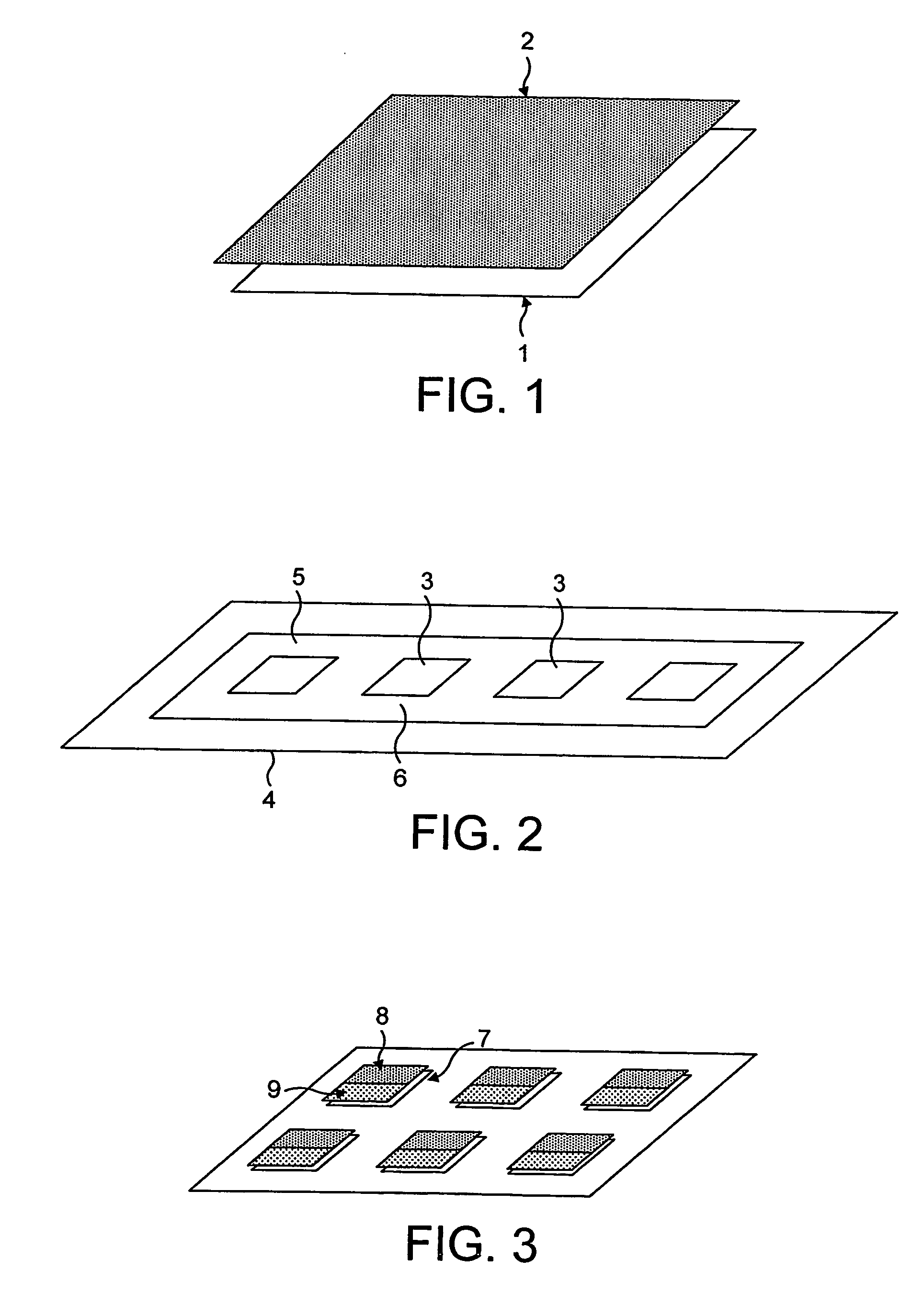
[0037] An explanation of these elements will first be given with reference to FIG. 1 of the accompanying drawings. A typical such a magnetic element will comprise a layer 1 of soft magnetic material, typically a magnetic alloy, characterised by a high permeability, low coercivity and a non-linear B-H characteristic, and formed as a discrete region of such material, combined with one or more layers 2 of a medium to high coercivity ferromagnetic material capable of being permanently magnetised. The first or high permeability magnetic element pr...


PUM


Abstract

Articles are magnetically tagged by a spatial distribution of passive magnetic elements. Each such magnetic element comprises a layer of soft magnetic material characterised by high permeability, low coercivity and a non-linear B-H characteristic, and formed as a discrete region of such material. Each such magnetic element also has at least one second layer of magnetic material capable of being permanently magnetised at least in a region adjacent the first layer to provide a magnetic bias for the magnetic element. The bias of individual such magnetic elements in the spatial distribution and the particular spatial nature of the distribution enables the article to be magnetically encoded.

Description

BACKGROUND OF THE INVENTION [0001] This invention relates to magnetic tagging. [0002] More particularly, in different but related aspects thereof, this invention relates to articles comprising magnetic tags, to magnetically tagged articles, to systems comprising such articles and a reading and / or writing assembly therefor, to mating or interlocking first and second parts with means preventing inadvertent re-use of second parts that had been previously used, to methods for encoding a plurality of articles, to methods for correct registration of a first part with a second part, and to methods preventing re-use of a disposable part adapted for mating or interlocking with a second part. [0003] Various non-contact identification systems are currently available. The most extensively used is the optical bar code which has the advantage that the tags can be produced in large quantities at low cost by a printing process. It is easy to copy the tag and once printed the code cannot be altered....

Claims


Application Information

Patent Timeline
IPC IPC(8): G08B1/00G01V15/00
CPCG01V15/00
Inventor ARNOLD, DAVID HOWARDDICKINSON, ROBERT JULIAN
Owner ADVOTEK MEDICAL DEVICES
Learn More