Liquid crystal device and method for forming the same

a liquid crystal and device technology, applied in the field of liquid crystal devices, can solve the problems of not being used to fabricate high-quality display devices, difficult cell manufacturing, increase the cost, etc., and achieve the effect of wide viewing angle, easy manufacturing, and better or high contrast ratio

Inactive Publication Date: 2007-11-22
IND TECH RES INST
View PDF21 Cites 10 Cited by
  • Summary
  • Abstract
  • Description
  • Claims
  • Application Information

AI Technical Summary

Benefits of technology

[0022]The liquid crystal composite of the liquid crystal device of the present invention comprises liquid crystal molecules and fine-particles, and the liquid crystal composite is optically isotropic when the voltage applied to the electrode layer is lower than a threshold value and undergoes optical transition due to change in the arrangement of the liquid crystal molecules when the applied voltage is equal to or higher than the threshold value. Therefore, the liquid crystal device of the present invention has a better or high contrast ratio and displaying quality without requiring any alignment processes or alignment l

Problems solved by technology

The cell is difficult to manufacture due to the complicate structure and process which in turn increase the cost.
Although all of the above encapsulated methods are promising to

Method used


Image

  • Liquid crystal device and method for forming the same
  • Liquid crystal device and method for forming the same
  • Liquid crystal device and method for forming the same

Examples


first embodiment (

Micro-Cup LCD Panel)

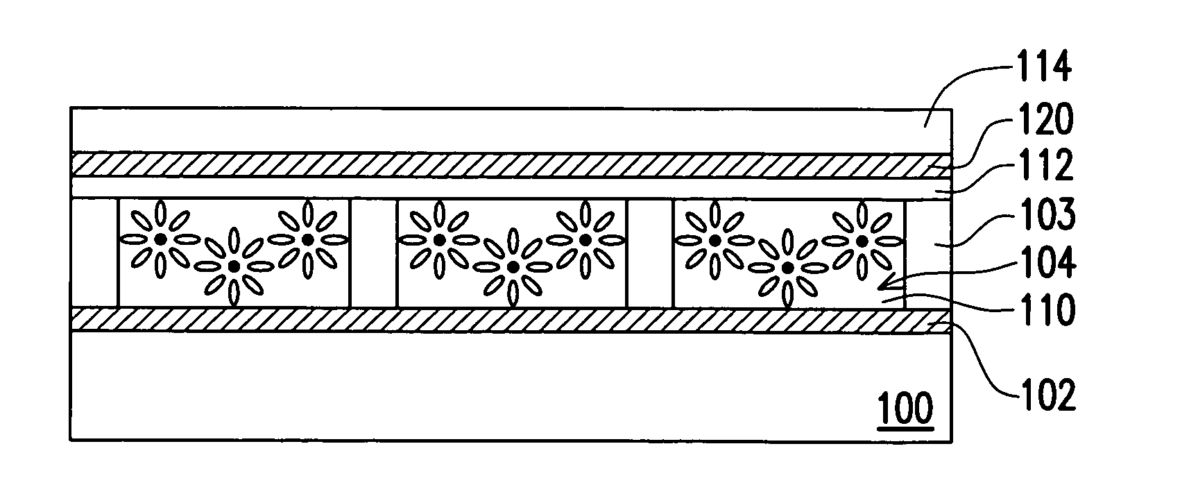
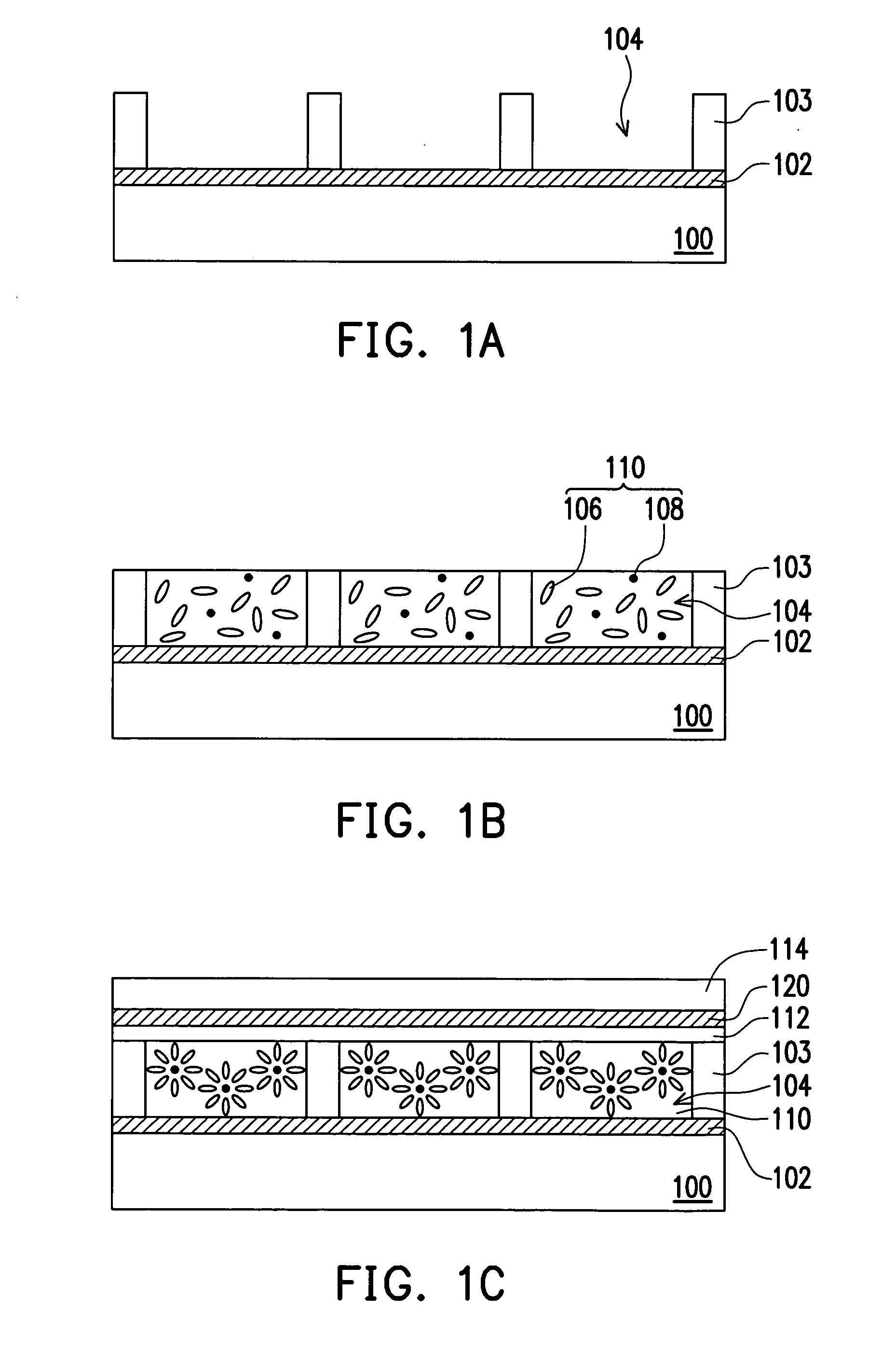
[0037]FIGS. 1A-1C are cross-sectional views showing a method of manufacturing a micro-cup liquid crystal device according to an embodiment of the present invention. Please refer to FIG. 1A, a substrate 100 is provided. The substrate 100 is, for example, a flexible substrate such as a plastic substrate. However, the substrate 100 is not particularly restricted, and it can be a rigid substrate, such as a glass substrate. An electrode layer 102 is formed on the substrate 100. The electrode layer 102 shown in the drawing is formed on the top surface of the substrate 100. The electrode layer 102 is made from indium tin oxide (ITO) or indium zinc oxide (IZO), for example. The material of the electrode layer 102 can also be an organic conductive material. According to an embodiment, the layer 102 may further comprise a device array. In details, if the liquid crystal device fabricated by the method of the present invention is an active matrix liquid crystal device, the l...

second embodiment (

Phase Separation LCD Panel)

[0046]FIG. 4 is a cross-sectional view showing a phase separation liquid crystal device according to an embodiment of the present invention. As shown in FIG. 4, the phase separation liquid crystal device comprises a liquid crystal composite 110, a substrate 100 having an electrode layer 102 thereon, a counter electrode 132 and a covering layer 130. In particular, the liquid crystal composite 110 comprises liquid crystal molecules 106 and fine-particles 108. The substrate 100 having the electrode layer 102 is at a side of the liquid crystal composite 110 and confining the liquid crystal composite 110. The covering layer 130 is disposed adjacent to the liquid crystal composite 110 for covering the liquid crystal composite 110 at a side opposite to the substrate 100. The covering layer 130 is a polymer layer, for example. The counter electrode layer 132 is formed on an outside surface of the covering layer 130. As the drawing shown, the covering layer 130 con...

third embodiment (

Droplet Encapsulated LCD Panel)

[0053]FIG. 6 is a cross-sectional view showing a droplet encapsulated liquid crystal device according to an embodiment of the present invention. As shown in FIG. 6, the droplet encapsulated liquid crystal device comprises a plurality of droplets of liquid crystal composite 144a, 144b, 144c, a substrate 100 having an electrode layer 102 thereon and a covering layer 140. The covering layer 140 may also be a counter substrate. According to an embodiment of the present invention, a counter electrode 142 is further formed between the covering layer (or substrate) 140 and the liquid crystal composite 110.

[0054]In the droplet encapsulated liquid crystal device, the liquid crystal composite 110 in each droplet 144a or 144b or 144c includes liquid crystal molecules 106 and fine-particles 108. The alignment of liquid crystal molecules 106 is the same to that of the first embodiment shown in FIG. 3A and FIG. 3B. That is, when the voltage applied to the electrode ...


PUM

PropertyMeasurementUnit
Particle diameteraaaaaaaaaa
Electrical conductoraaaaaaaaaa
Selectivityaaaaaaaaaa

Abstract

The present invention generally relates to liquid crystal devices and methods for forming the same. More particularly, the present invention relates to liquid crystal devices easy to be fabricated. Such liquid crystal devices exhibit excellent display characteristics such as a high contrast with a simple structure. The liquid crystal liquid crystal device includes a plurality of encapsulated liquid crystal composite filled in between substrates. In particular, the liquid crystal composite comprises liquid crystal molecules and fine-particles, and is optically isotropic when the voltage applied to the electrode layer is lower than a threshold value and undergoes optical transition due to change in the arrangement of the liquid crystal molecules when the applied voltage is equal to or higher than the threshold value.

Description

BACKGROUND OF THE INVENTION[0001]1. Field of the Invention[0002]The present invention generally relates to liquid crystal devices and methods for forming the same. More particularly, the present invention relates to liquid crystal devices easy to be fabricated. Such liquid crystal devices can be applied to form an excellent display with a high contrast with a simple structure.[0003]2. Description of Related Art[0004]To fabricate a conventional liquid crystal display (LCD) panel, liquid crystal molecules are filled by vacuum filling and are sealed to form a liquid crystal cell comprising two sheets of transparent conductive substrates having an alignment layer applied thereto and a sealing layer provided between the substrates. The cell is difficult to manufacture due to the complicate structure and process which in turn increase the cost. Several methods have been proposed and implemented to reduce the manufacture process by encapsulating display media, such as by polymer dispersed ...

Claims


Application Information

Patent Timeline
IPC IPC(8): C09K19/52
CPCB29C35/0888B29C59/046B29C2035/0827B29K2105/0079B32B38/06G02F2202/36B82Y20/00C09K19/52G02F1/1303G02F1/133377B32B2457/202
Inventor JENG, SHIE-CHANGHSIN, LUNG-PINLIN, YAN-RUNGLIAO, CHI-CHANG
Owner IND TECH RES INST
Why Eureka
Try Eureka