Relay circuit

Inactive Publication Date: 2007-11-22
PENNY & GILES CONTROLS
View PDF3 Cites 5 Cited by
  • Summary
  • Abstract
  • Description
  • Claims
  • Application Information

AI Technical Summary

Benefits of technology

[0013]Preferably, the circuit further comprises a capacitor that is charged before said first

Problems solved by technology

The lifetime of the electrical contacts of relays is usually the limiting factor in determining their usefulness in modern circuits.
At higher voltages, the material from which the relay contacts are made behave differently and contact erosion through arcing during the opening and closing of the contacts becomes significant.
At higher voltages, for example 36-48V, the abil

Method used


Image

  • Relay circuit
  • Relay circuit
  • Relay circuit

Examples


Embodiment Construction

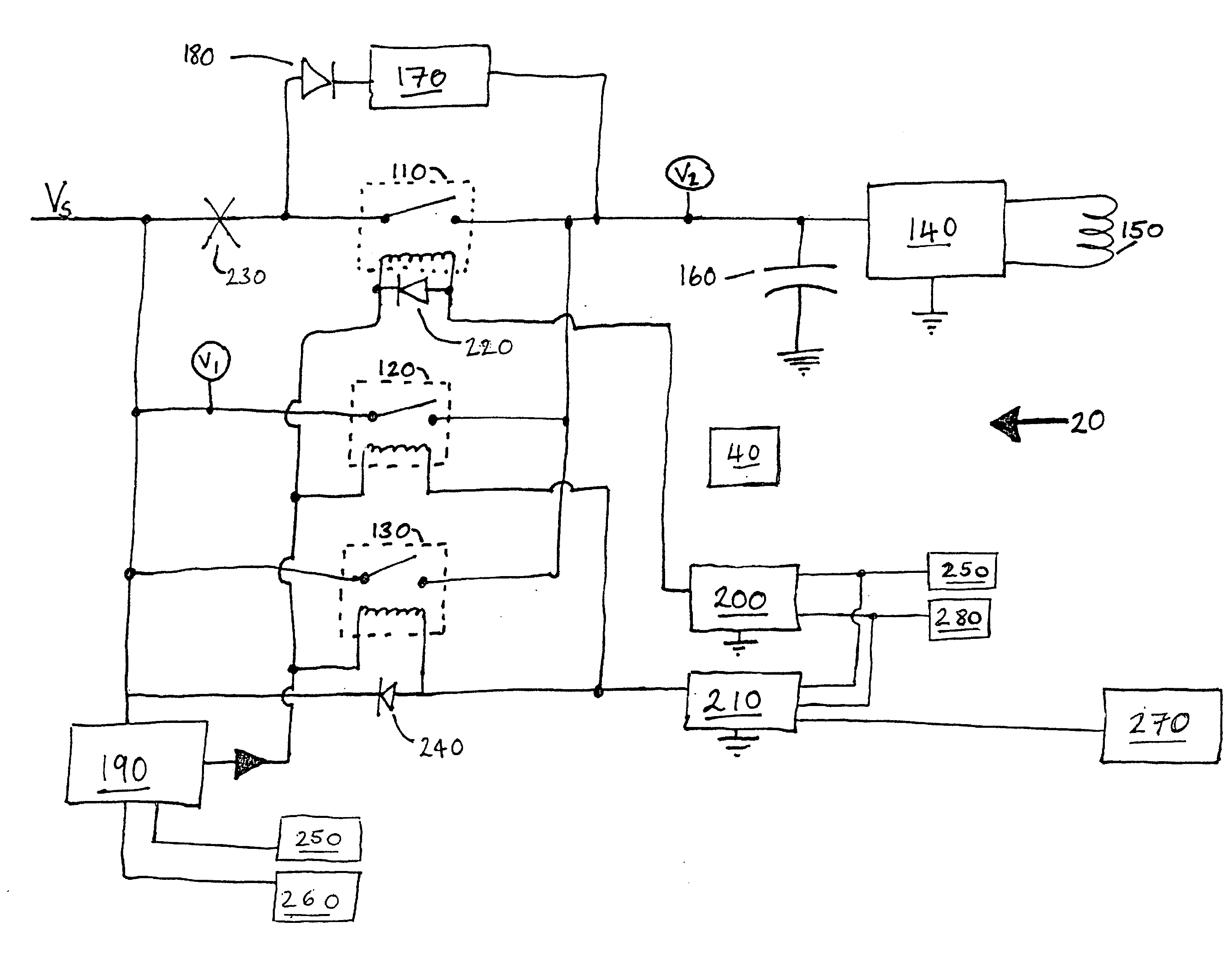
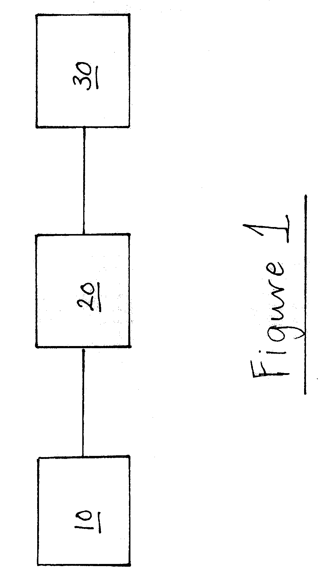
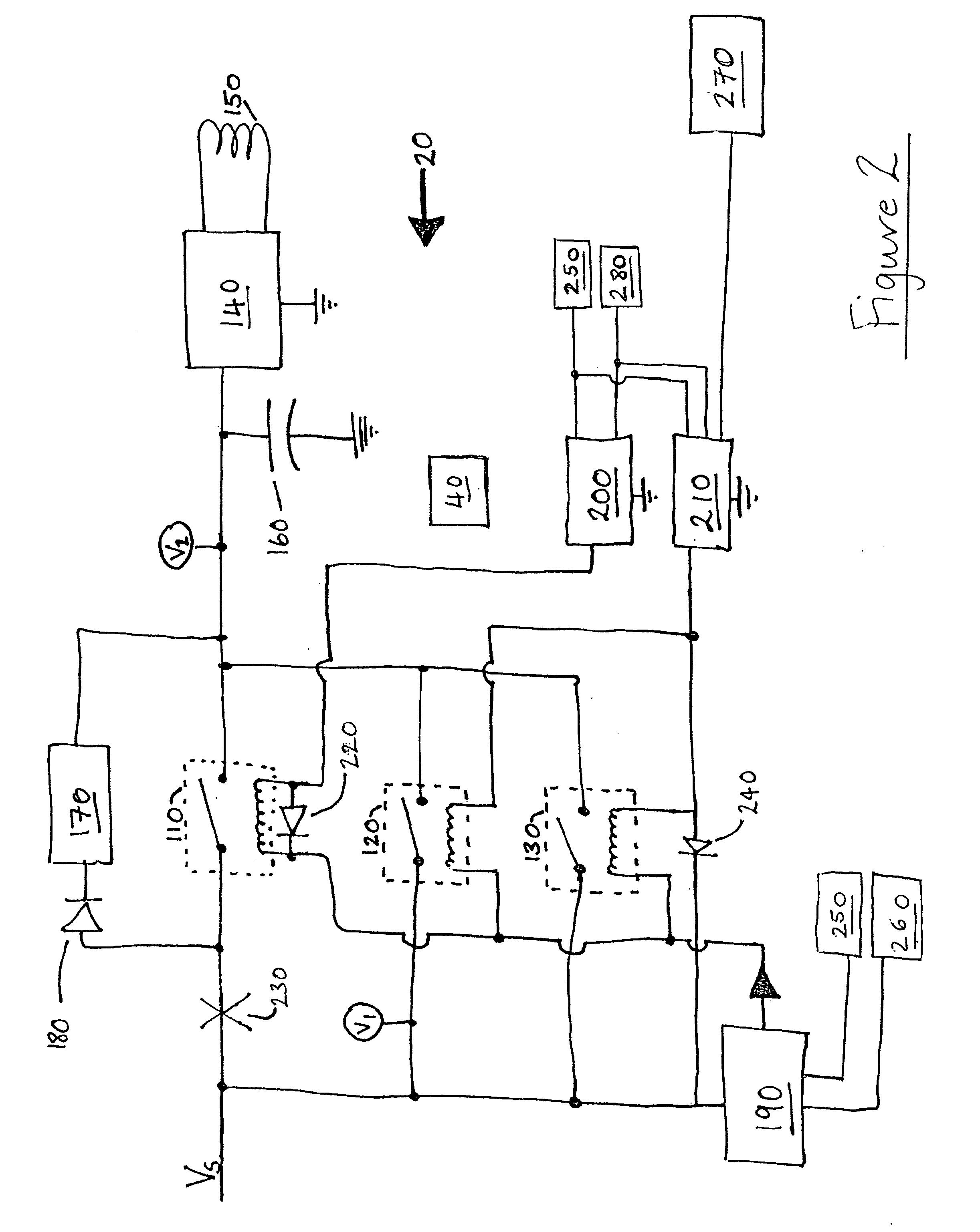
[0022]FIG. 1 illustrates the main components of a drive circuit for a battery powered vehicle, for example, a wheelchair. A battery supply 10, for example a 48V supply, is used to drive a wheelchair motor 30 via a switching circuit 20. In the event of an electrical fault it is necessary to reliably isolate the supply 10 from the motor 30 to prevent an unsafe condition from occurring.

[0023]The switching circuit 20 is shown in more detail in FIG. 2. The circuit 20 comprises a voltage supply Vs from the battery 10, a protective relay 110, first and second isolation relays 120, 130, and electronic drive circuitry 140 for a load 150, which in this example comprises the windings of the motors for the wheelchair.

[0024]The electronic drive circuitry 140 comprises a full or half bridge motor drive circuit (not shown) that is for driving the load 150 and is controlled by the protective relay 110 and the first and second relays 120, 130. The protective relay 110 and the first and second isolat...


PUM


Abstract

A switching circuit for connecting a power source to a load is described. The circuit comprises a first relay and at least one second relay in parallel arrangement with the first relay. The switching circuit is arranged such that in the event of a fault condition occurring that requires the disconnection of the power source from the load, the at least one second relay opens while the first relay remains closed. In this manner, a reliable disconnection of the load from the switching circuit is achieved.

Description

CROSS REFERENCE TO PRIORITY APPLICATION[0001]This application claims the benefit of UK Application No. 0609634.1 filed 16 May 2006, incorporated herein by reference in its entirety.BACKGROUND OF THE INVENTION[0002]The present invention is concerned with electronic switching circuits comprising electromechanical relays and particularly but not exclusively to switching circuits for isolating electrical loads in the event of a fault.[0003]Electromechanical relays are a very mature technology. Despite being replaced by semiconductor devices in many applications, the basic relay still retains many advantages over modern switching systems providing an inherently low voltage drop and good electrical isolation.[0004]The lifetime of the electrical contacts of relays is usually the limiting factor in determining their usefulness in modern circuits. This is especially true for direct current (DC) applications where contact erosion takes place. The rated useful life of the relay contacts is oft...

Claims


Application Information

Patent Timeline
IPC IPC(8): H02H3/00A61G5/04
CPCH02H7/222A61G5/04H02H3/033H02P1/023H02H7/0811
Inventor BRERETON, RICHARD PETERHAMILTON, DUNCANREES, DANIEL ROBERT
Owner PENNY & GILES CONTROLS
Why Eureka
Try Eureka