Moving-picture coding apparatus, method and program, and moving-picture decoding apparatus, method and program

a moving picture and coding technology, applied in the field of moving picture moving picture decoding apparatus, method and program, can solve the problems of low texture data quality, insufficient mitigation of discontinuous situation between blocks, and inability to reduce the degree of smoothing required

Active Publication Date: 2007-11-22
ADVANCED CODING TECH LLC
View PDF12 Cites 17 Cited by
  • Summary
  • Abstract
  • Description
  • Claims
  • Application Information

AI Technical Summary

Benefits of technology

[0011] A purpose of the present invention is to provide a moving-picture coding apparatus, method and program, and a moving-picture decoding apparatus, method and program that, without a smoothing procedure, can produce...

Problems solved by technology

The discontinuous situation between blocks may, however, not be mitigated enough, which depends on the degree of smoothing.
For example, a lower degree of smoothing than required cannot mitigate enough a discontinuous situation between blocks which thus remains as block distortion.
In contrast, a higher degree of smoothing than required can mitigat...

Method used


Image

  • Moving-picture coding apparatus, method and program, and moving-picture decoding apparatus, method and program
  • Moving-picture coding apparatus, method and program, and moving-picture decoding apparatus, method and program
  • Moving-picture coding apparatus, method and program, and moving-picture decoding apparatus, method and program

Examples


embodiment i

[0040] Disclosed first are first embodiments of a moving-picture coding apparatus, a moving-picture decoding apparatus, and their corresponding methods according to the present invention.

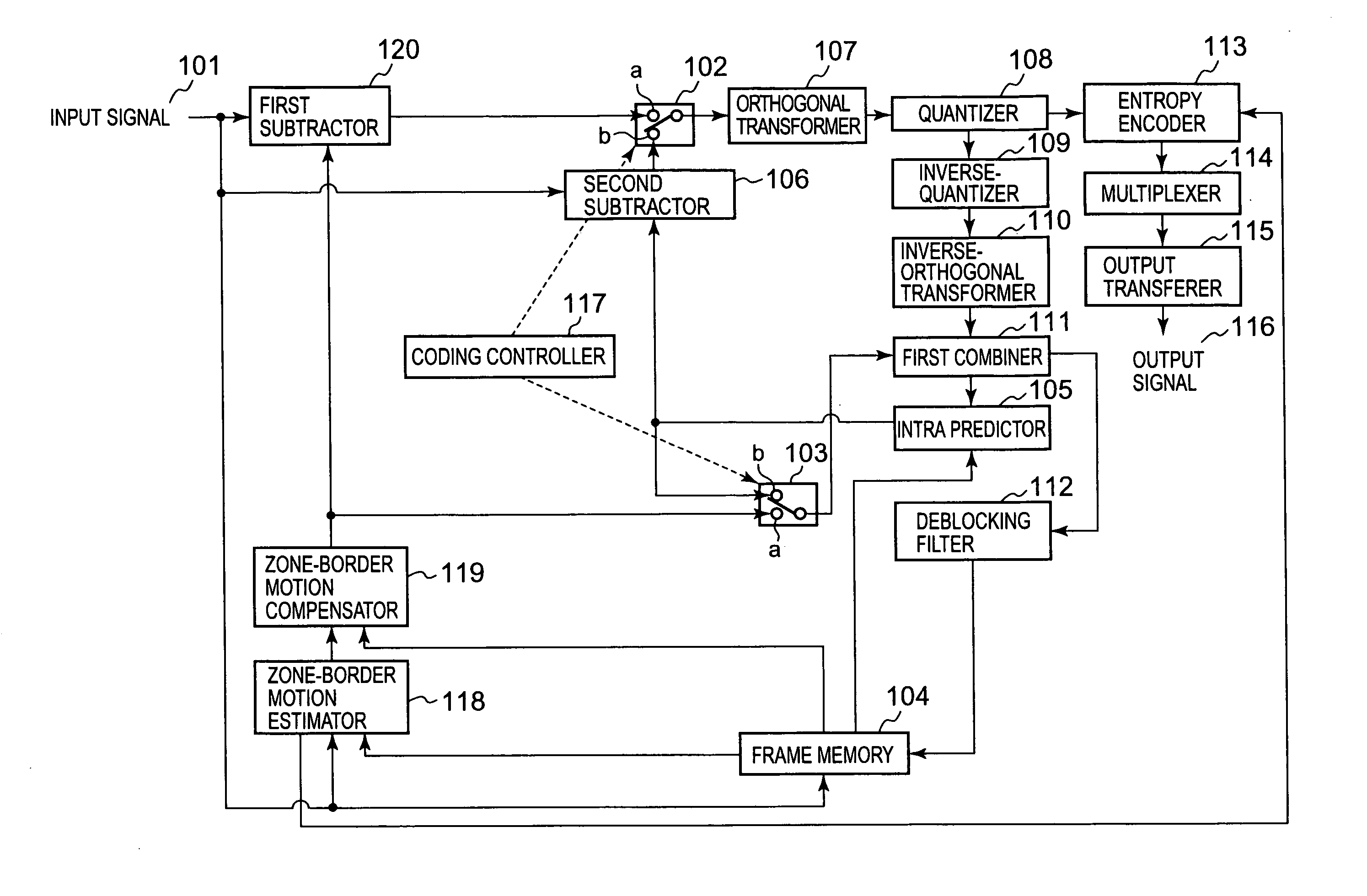
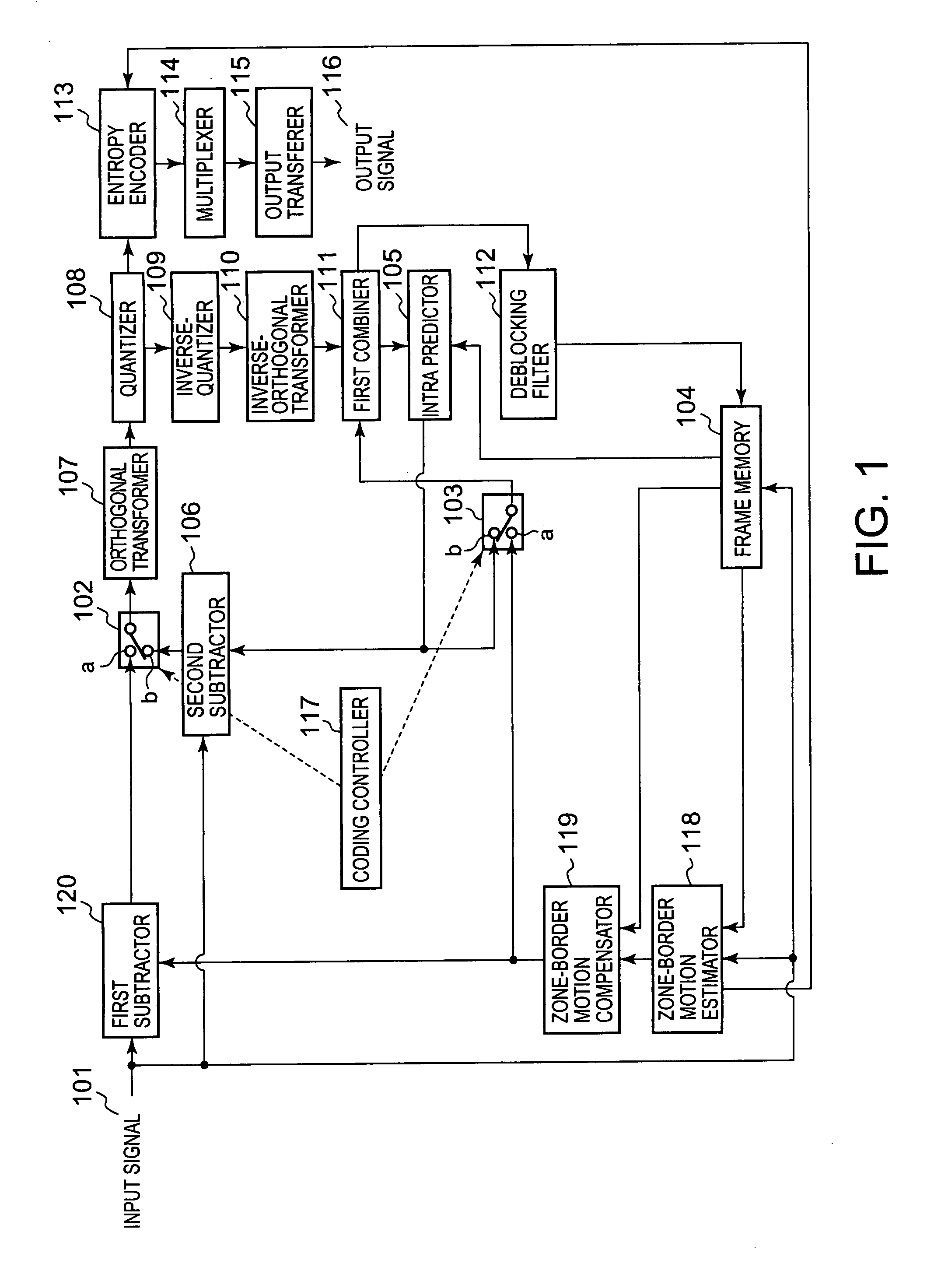
[0041]FIG. 1 shows a block diagram of a first embodiment of a moving-picture coding apparatus according to the present invention. As shown in FIG. 1, the coding apparatus in this embodiment is equipped at least with a switch 102, a switch 103, a frame memory 104, a second subtractor 106, an orthogonal transformer 107, a quantizer 108, an inverse-quantizer 109, an inverse-orthogonal transformer 110, a first combiner 111, an entropy encoder 113, a multipixer 114, an output transferer 115, a coding controller 117, a zone-border motion estimator 118, a zone-border motion compensator 119, and a first subtractor 120. Moreover, it is preferable for the coding apparatus to be equipped with an intra predictor 105 and a deblocking filter 112, as shown in FIG. 1. This embodiment features the zone-border motio...

embodiment ii

[0138] Disclosed next are second embodiments of a moving-picture coding apparatus and a moving-picture decoding apparatus according to the present invention.

[0139]FIG. 5 shows a block diagram of the second embodiment of the moving-picture coding apparatus according to the present invention. In the figure, the component parts analogous to those in FIG. 1 are given the same reference numerals, with detailed explanation thereof being omitted. In addition to the component parts analogous to those of the moving-picture coding apparatus of FIG. 1, the moving-picture coding apparatus in this embodiment is equipped a switch 501, a motion estimator 502, a motion compensator 503, and a residual determiner 504, for motion estimation and compensation in H. 264 / AVC.

[0140] There are three prediction modes in AVC: intra predictive coding, forward predictive coding, and bidirectional predictive coding.

[0141] In intra predictive coding, orthogonal transform is performed at the orthogonal transfor...

embodiment iii

[0202] The present invention is not limited to the above embodiment I or II, but also includes programs that achieve the functions of the coding apparatus in FIG. 1 or FIG. 5, and the functions of the decoding apparatus in FIG. 3 or FIG. 7, on a central processing apparatus that is a computer shown in FIGS. 9 to 12, the programs being described as follows.

[0203]FIG. 9 is a block diagram of a data processing system operated with a first embodiment of a moving-picture coding program according to the present invention. The data processing system 900 is equipped with: an input unit 901 for entering several kinds of data; an output unit 902 for outputting several kinds of data; a central processing and controlling unit 903 that runs on the first embodiment of the moving-picture coding program according to the present invention; an external memory unit 904; a temporary memory unit 905 to be used, for example, as a working area in processing at the central processing and controlling unit ...


PUM


Abstract

A residual picture is produced and encoded that is a residual picture that is a residual signal between a picture to be coded that is an input moving-picture video signal to be subjected to coding and a predictive picture produced from a reference picture that is a local decoded video signal for each of a plurality of rectangular zones, each composed of a specific number of pixels, into which a video area of the moving-picture video signal is divided. A boundary condition of each of a plurality of borders is obtained between the rectangular zones and another plurality of rectangular zones adjacent to the rectangular zones, and a border, of the reference picture, having a boundary condition that matches the boundary condition, is found by motion-vector search in the reference picture, and border motion-vector data is generated that is data on a motion vector from a border of the rectangular zone in the picture to be coded to the border of the reference picture thus found. A boundary condition of a border that corresponds to the border motion vector data is defined from the reference picture based on the border motion-vector data, and an estimated video signal is generated in each rectangular zone in the picture to be coded, that satisfies Poisson's Equation, thus producing a first predictive picture. The residual picture is then produced with the first predictive picture as the predictive picture and encodes the residual picture.

Description

CROSS-REFERENCE TO RELATED APPLICATIONS [0001] This application is based on and claims the benefit of priority from the prior Japanese Patent Application Nos. 2006-112995 filed on Apr. 17, 2006 and 2007-93162 filed on Mar. 30, 2007, the entire contents of which are incorporated herein by reference. BACKGROUND OF THE INVENTION [0002] The present invention relates to a moving-picture coding apparatus, method and program, and a moving-picture decoding apparatus, method and program, with a boundary condition obtained between moving-picture blocks and applied for coding or decoding. [0003] Several types of video broadcast services via digital broadcasts or networks are popular now. This creates a demand for higher moving-picture coding efficiency for recording a larger amount of moving pictures at a higher picture quality and definition. [0004] There are now several new coding methods, such as, MPEG-4 AVC (which will be referred to as AVC or H. 264, hereinafter) with drastically higher c...

Claims


Application Information

Patent Timeline
IPC IPC(8): H04N11/04H04N19/50H04N19/105H04N19/134H04N19/136H04N19/137H04N19/14H04N19/147H04N19/167H04N19/189H04N19/196H04N19/503H04N19/51H04N19/523H04N19/537H04N19/543H04N19/567H04N19/57H04N19/573H04N19/593H04N19/60H04N19/61H04N19/625H04N19/63H04N19/82H04N19/86H04N19/91H04N19/93
CPCH04N19/176H04N19/70H04N19/13H04N19/61H04N19/55H04N19/124H04N19/91H04N19/14H04N19/103
Inventor SAKAZUME, SATORU
Owner ADVANCED CODING TECH LLC
Why Eureka
Try Eureka