
Manufacturing method of semiconductor device

Inactive Publication Date: 2007-11-22
ELPIDA MEMORY INC
View PDF1 Cites 3 Cited by
  • Summary
  • Abstract
  • Description
  • Claims
  • Application Information

AI Technical Summary

Benefits of technology

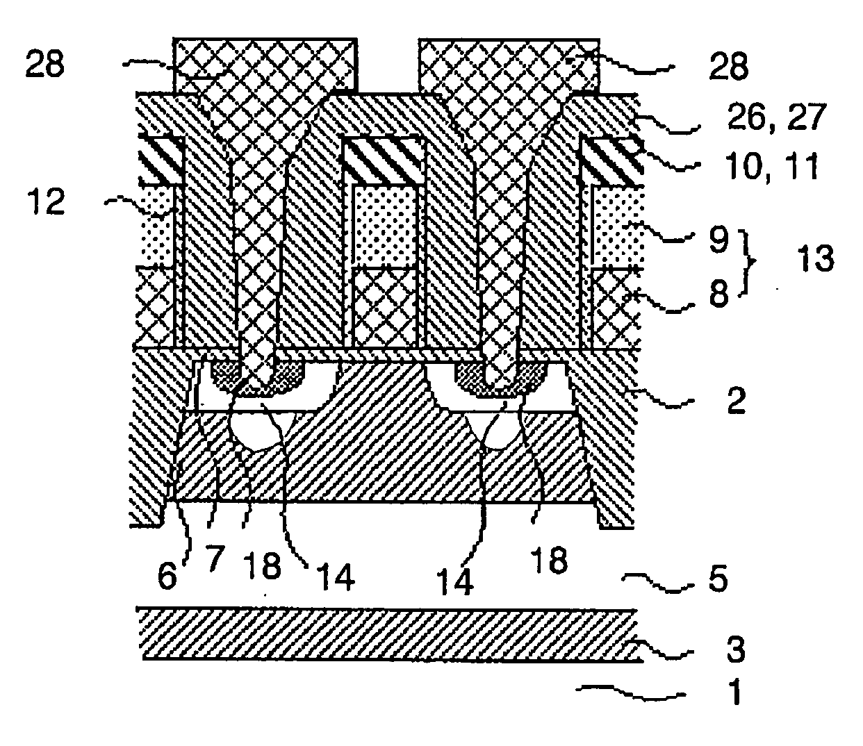
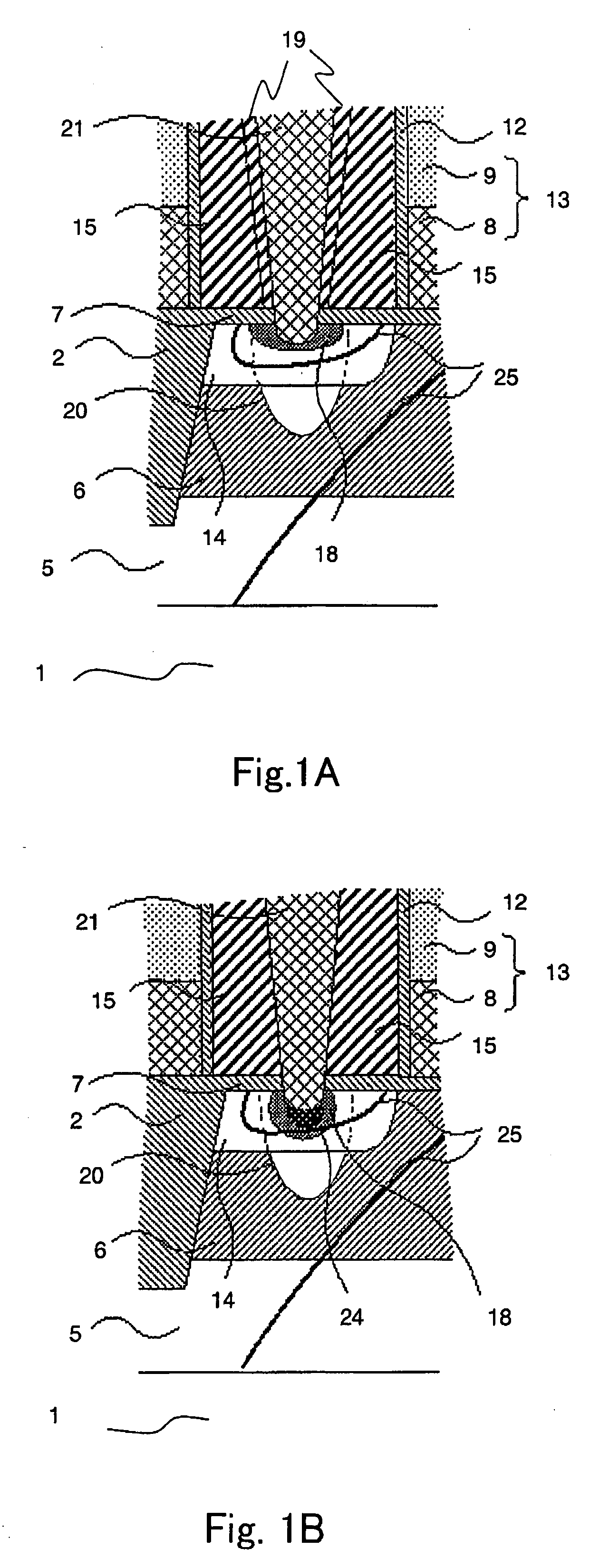
[0019]According to the method for manufacturing a semiconductor device of the present invention, arsenic ion implantation is performed after formation of a contact hole for reducing the series resistance, and then a sidewall film is formed on a side surface defining the contact hole. Silicon is etched away by using the sidewall film as a mask to thereby remove the region containing many implantation damages around the projected range position of arsenic while leaving unetched the arsenic region directly below the sidewall film. The removal of the secondary defect region having many implantation damages is effective to suppress the remaining of secondary defects and to prevent occurrence of junction leak current. When the present invention is applied to a DRAM cell transistor, the probability of remaining of implantation defects can be reduced. The DRAM refresh time is improved and the refresh defective rate is reduced. As a result, the method for manufacturing a semiconductor device of the present invention has high reliability and high manufacture yield.

Problems solved by technology

The contact between the defects and a depletion layer will induce a problem of junction leakage.

Method used


Image

  • Manufacturing method of semiconductor device
  • Manufacturing method of semiconductor device
  • Manufacturing method of semiconductor device

Examples


Embodiment Construction

[0025]A method for manufacturing a semiconductor device according to the present invention will be described with reference to the accompanying drawings.

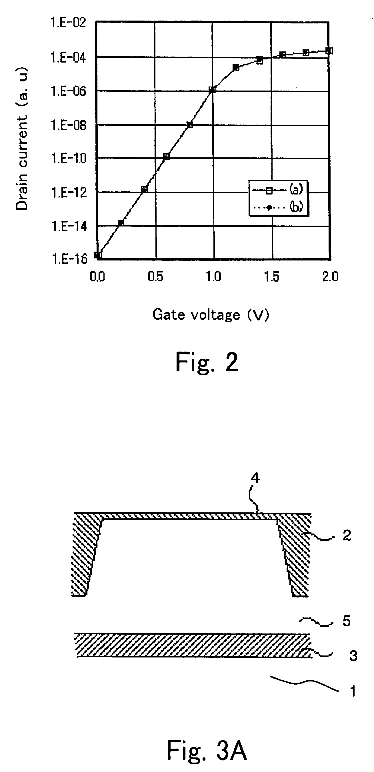
[0026]A first embodiment of the present invention will be described in detail with reference to the drawings. FIGS. 1A and 1B are cross-sectional views showing the vicinity of a drain according to a first embodiment and a related art, respectively. FIG. 2 is a diagram illustrating gate voltage dependency of drain current. FIGS. 3A to 3L are cross-sectional views showing primary steps according to the first embodiment of the present invention. FIG. 5 is a diagram illustrating correlation between refresh time and fraction defective.

[0027]Referring to these drawings, a manufacturing method according to the first embodiment will be described. To obtain a state shown in FIG. 3A, a groove is formed in a surface of a silicon substrate 1. The groove is filled with an insulation film 2 to separate elements and to isolate an active region. Su...


PUM


Abstract

A method for manufacturing a semiconductor device is provided, which is capable of solving a junction leakage problem. According to the manufacturing method of the present invention, arsenic is implanted to reduce the series resistance after formation of a contact hole. A sidewall film is then formed on the side surface defining the contact hole. Silicon is etched by using the sidewall film as a mask to thereby remove the region containing many implantation damages around the projected range position of arsenic while leaving unetched the arsenic region directly below the sidewall film. The removal of the secondary defect region having many implantation damages is effective to prevent occurrence of junction leak current.

Description

[0001]This application claims priority to prior Japanese application JP 2006-141894, the disclosure of which is incorporated herein by reference.BACKGROUND OF THE INVENTION[0002]The present invention relates to a manufacturing method of a semiconductor device and, in particular, to a manufacturing method of a semiconductor device which causes less junction leak current.[0003]Element patterns have been made finer and finer along with the increase of the integration density of semiconductor devices. For example, dynamic random access memories (hereafter, referred to as “DRAMs”) with a capacity of 1 GB have been commercialized and put to practical use. Manufacturing methods of these large-capacity DRAMs have been improved in various manners to cope with the refinement of element dimensions.[0004]In one of these improved manufacturing methods, ions having a short projected range position are implanted after formation of a contact hole to reduce the contact resistance in a source / drain p...

Claims


Application Information

Patent Timeline
IPC IPC(8): H01L21/265
CPCH01L21/26513H01L21/28512H01L21/76814H01L21/76831H01L23/485H01L2924/0002H01L29/66636H01L2924/00H01L21/76897H01L21/76805
Inventor TAKETANI, HIROAKI
Owner ELPIDA MEMORY INC
Learn More