
Improved P-type PERC (Passivated Emitter Rear Contact) two-sided solar cell and preparation method thereof

A solar cell and an improved technology, applied in the field of solar cells, can solve problems such as high cost and complicated process, and achieve the effect of low equipment investment cost, simple preparation process, and suitable for wide promotion and application

Inactive Publication Date: 2017-06-20
ZHEJIANG AIKO SOLAR ENERGY TECH CO LTD
View PDF6 Cites 3 Cited by
  • Summary
  • Abstract
  • Description
  • Claims
  • Application Information

AI Technical Summary

Problems solved by technology

However, the current research on double-sided PERC solar cells is only limited to the research and development done by some research institutions in the laboratory, which has the disadvantages of complex process and high cost.

Method used


Image

  • Improved P-type PERC (Passivated Emitter Rear Contact) two-sided solar cell and preparation method thereof
  • Improved P-type PERC (Passivated Emitter Rear Contact) two-sided solar cell and preparation method thereof
  • Improved P-type PERC (Passivated Emitter Rear Contact) two-sided solar cell and preparation method thereof

Examples


Embodiment 1

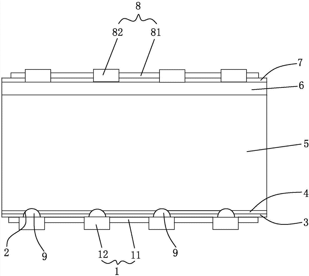
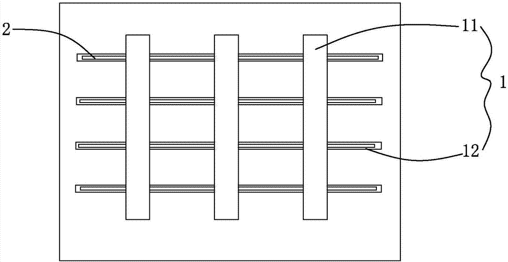
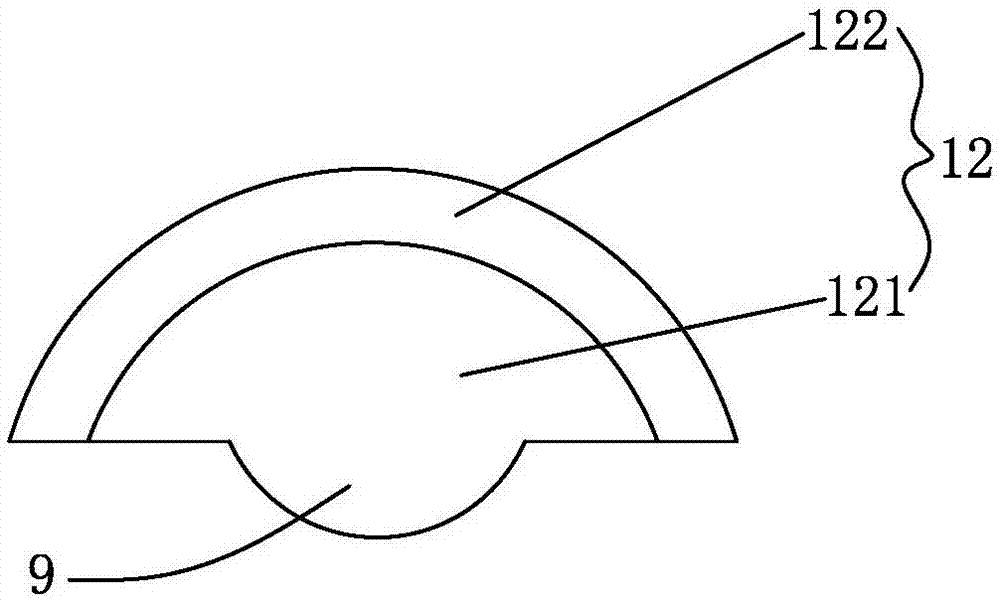
[0045] Such as Figure 1~3 As shown, it is an improved double-sided P-type PERC solar cell of the present invention, including a back electrode 1, a back silicon nitride film 3, an aluminum oxide film 4, a P-type silicon 5, and an N-type emitter arranged sequentially from bottom to top. 6. The front silicon nitride film 7 and the front silver electrode 8, the front silver electrode 8 is mainly formed by connecting the front silver electrode sub-grid 82 and the front silver electrode main grid 81 which are vertically intersecting. The back electrode 1 is mainly formed by connecting the back electrode main gate line 11 and the back electrode sub-gate line 12 which are vertically intersecting. On the back silicon nitride film 3, there is an opening through the back silicon nitride film 3 and the aluminum oxide film 4. Slot 2, P-type silicon 5 is exposed in slot 2, back electrode auxiliary grid line 12 is mainly composed of back aluminum grid line 121 and back silver grid line 122...

Embodiment 2

[0061] Such as Figure 4 As shown, the difference between this embodiment and Embodiment 1 is that each group of slots 2 is vertically arranged and arranged in parallel, and the slots 2 and the back electrode sub-gate line 12 are perpendicular to each other. The part of the aluminum gate line 121 located in the slot is connected to the P-type silicon.

Embodiment 3

[0063] Such as Figure 5 As shown, the difference between this embodiment and Embodiment 1 is that each group of slots 2 is composed of several rows of slots arranged in parallel in the transverse direction, and each row of slots is composed of several sections of slots arranged in parallel in the longitudinal direction.


PUM

PropertyMeasurementUnit
Thicknessaaaaaaaaaa
Thicknessaaaaaaaaaa
Thicknessaaaaaaaaaa

Abstract

The invention discloses an improved P-type PERC (Passivated Emitter Rear Contact) two-sided solar cell and a preparation method thereof. The two-sided solar cell comprises a rear electrode, a rear silicon nitride film, an alumina film, P-type silicon, an N-type emitter, a front silicon nitride film and a front silver electrode which are sequentially arranged from the bottom up, wherein the rear electrode is mainly formed by connecting rear electrode main grid lines and rear electrode auxiliary grid lines which are orthogonal; grooves penetrating through the rear silicon nitride film and the alumina film are formed in the rear silicon nitride film; the P-type silicon is exposed in the grooves; the rear electrode auxiliary grid lines mainly consist of rear aluminum grid lines and rear silver grid lines; the rear aluminum grid lines located in the grooves are connected with the P-type silicon; and the rear silver grid lines are arranged on the external surfaces of the rear aluminum grid lines exposed out of the grooves. According to the two-sided solar cell, the conductivity of the original rear electrode auxiliary grid lines can be improved; the series resistance of the two-sided solar cell can be reduced; the photoelectric conversion efficiency of the two-sided solar cell can be improved; a preparation technology is simple; the equipment input cost is low; and the compatibility with the existing production line is good.

Description

technical field [0001] The invention relates to solar cell technology, in particular to an improved P-type PERC double-sided solar cell, and also to a preparation method of the improved P-type PERC double-sided solar cell. Background technique [0002] A crystalline silicon solar cell is a device that effectively absorbs solar radiation energy and converts light energy into electrical energy by using the photovoltaic effect. When sunlight shines on the semiconductor P-N junction, new hole-electron pairs will be formed. Under the action of the electric field of the P-N junction, the holes flow from the N region to the P region, and the electrons flow from the P region to the N region. After the circuit is turned on A current is formed. [0003] Traditional crystalline silicon solar cells generally only use front passivation technology, using PECVD to deposit a layer of silicon nitride on the front surface of the silicon wafer, reducing the recombination rate of minority carr...

Claims


Application Information

Patent Timeline
IPC IPC(8): H01L31/0224H01L31/042H01L31/18
CPCH01L31/022441H01L31/042Y02E10/50Y02P70/50
Inventor 方结彬何达能陈刚
Owner ZHEJIANG AIKO SOLAR ENERGY TECH CO LTD
Learn More