Electric motor

a technology of electric motors and motors, applied in the direction of bearing cooling, magnetic circuit rotating parts, magnetic circuit shape/form/construction, etc., can solve the problems of obstructing the smooth rotation of bearings, reducing the viscosity of oil, and unable to satisfy the cooling of bearings, so as to reduce the size and complexity of electric motors, reduce the size of oil, and reduce the cost

Inactive Publication Date: 2007-11-29
MITSUBISHI ELECTRIC CORP
View PDF13 Cites 36 Cited by
  • Summary
  • Abstract
  • Description
  • Claims
  • Application Information

AI Technical Summary

Benefits of technology

[0010]Accordingly, the present invention is intended to obviate the problems as referred to above, and has for its object to obtain an electric motor with a bearing structure which is capable of efficiently cooling bearings with a simple...

Problems solved by technology

That is, when a large amount of heat generated by the rotor rotating at high speed is transmitted through thermal conduction to the bearings by way of the rotor shaft, satisfactory cooling of the bearings can not be performed, so the temperature of oil in the vicinity of the bearings rises and the viscosity of oil decreases, thus obstructing smooth rotation of the bearings.
Further, there is another problem that when a predetermined temperature decided by the material of the bearings is exceeded, the reduction or degradati...

Method used


Image

  • Electric motor
  • Electric motor
  • Electric motor

Examples


embodiment 1

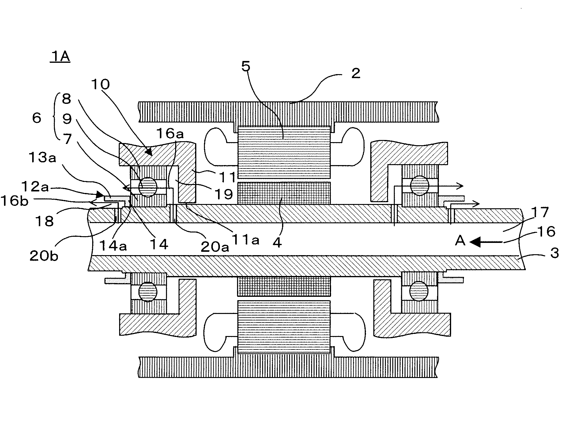
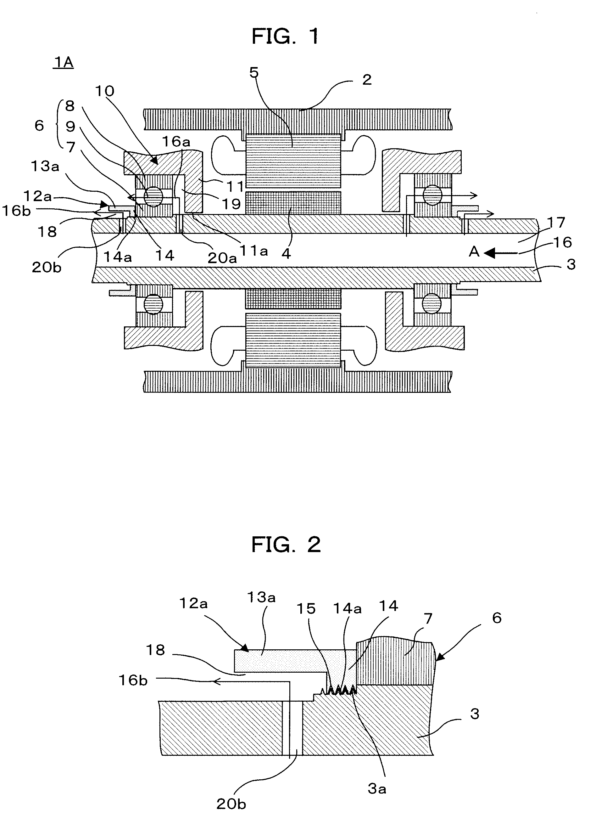
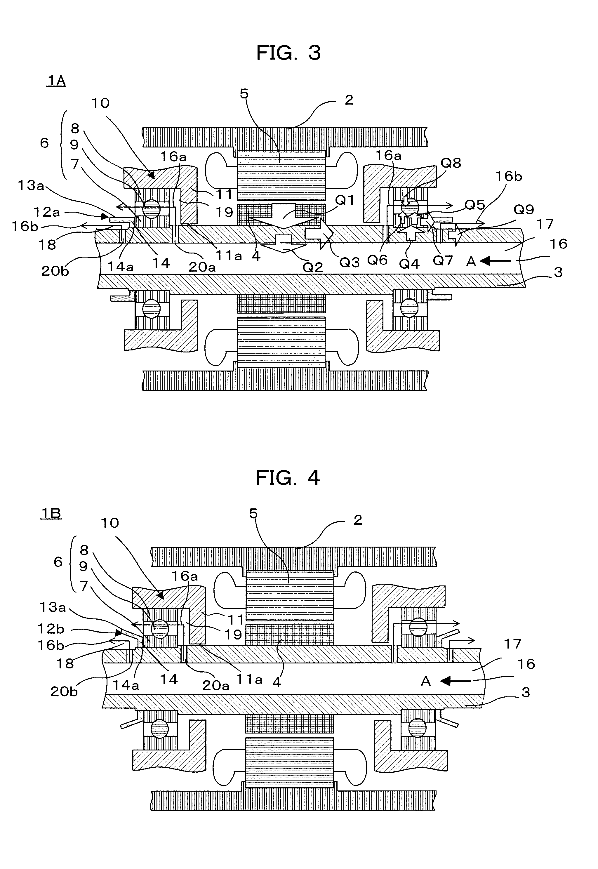
[0021]Referring to the drawings and first to FIG. 1, there is shown, in a cross sectional view, the construction of an electric motor according to a first embodiment of the present invention. FIG. 2 is an enlarged cross sectional view of an installation part of a cooling ring in FIG. 1, showing a state in which the cooling ring and a rotor shaft are in threaded engagement with each other. FIG. 3 is a schematic diagram explaining the transfer of heat in the electric motor according to the first embodiment of the present invention.

[0022]In FIGS. 1 and 2, an electric motor 1A includes a casing 2 in which there are individually arranged a rotor shaft 3, a cylindrical rotor 4, a cylindrical stator 5 having an inner diameter larger than an outer diameter of the rotor 4, a pair of bearings in the form of ball bearings 6, a pair of bearing fixing parts 10, and a pair of bearing cooling devices in the form of a pair of cooling rings 12a.

[0023]The rotor shaft 3 has a hollow bore 17 formed th...

embodiment 2

[0050]FIG. 4 is a cross sectional view that shows the construction of an electric motor according to a second embodiment of the present invention.

[0051]In FIG. 4, a heat dissipation portion 13a in a cooling ring 12b in the form of a bearing cooling device of an electric motor 1B takes a mouth-opened shape in which the radial width of a ring gap 18 gradually increases from an end face of an inner race 7 of a bearing 6 at a side opposite to a rotor 4 toward a side opposite to the bearing 6 (i.e., in a direction toward an opening of the cooling ring 12b). Here, note that the construction of this embodiment other than the above is similar to that of the above-mentioned first embodiment.

[0052]In this second embodiment, the radial width of the ring gap 18 gradually broadens in a direction toward the opening of the cooling ring 12b, and hence the opening area of the cooling ring 12b, serving as a discharge port for the lubricating oil 16b, also increases, so the lubricating oil 16b directe...

embodiment 3

[0057]FIG. 5 is a cross sectional view that shows the construction of an electric motor according to a third embodiment of the present invention.

[0058]In an electric motor 1C according to this third embodiment, the distance between a first bottom portion 11 and a ball bearing 6 of a bearing fixing part 10 is set large so that a space 19 is formed wide in the direction of the axis of rotation of the rotor 4, and a cooling ring 12c, which acts as a bearing cooling device and is similar in shape to the cooling ring 12a, is threaded over a rotor shaft 3 at a rotor side of each ball bearing 6 with its opening directed to the rotor 4. At this time, the cooling ring 12c has an outer wall of a second bottom portion 14 placed in intimate contact with a rotor side end face of an inner race 7 of each ball bearing 6. Also, a third through hole 20c, acting as a communication hole, is formed through the rotor shaft 3 in a radial direction thereof so that a ring gap 18 of the cooling ring 12c and ...


PUM


Abstract

An electric motor includes a rotor shaft arranged in a casing and having an axial hollow bore formed therethrough for passage of lubricating oil, a rotor, a stator, a pair of bearings each having an inner race and an outer race, a pair of bearing fixing parts supporting the rotation of the rotor shaft, and bearing cooling devices each having a cylindrical heat dissipation portion fixedly secured to the rotor shaft so as to be in contact with either one of end faces of the individual inner races, the heat dissipation portion extending from the one end face of each inner race to a side opposite to the bearings. A pair of spaces between rotor-side end faces of the bearings and the bearing fixing parts, respectively, are in communication with ring gaps between the heat dissipation portions and the rotor shaft, respectively, through radial communication holes in the rotor shaft.

Description

BACKGROUND OF THE INVENTION[0001]1. Field of the Invention[0002]The present invention relates to an electric motor for use with an electric vehicle or the like, and in particular, to a bearing structure which is capable of cooling bearings that support a rotor shaft in such an electric motor to a satisfactory extent.[0003]2. Description of the Related Art[0004]A known drive unit for an electric vehicle is provided with a motor, a casing having the motor received therein, an oil circulation system that circulates oil for cooling the motor in the casing, and a cooling system that cools the oil circulating in the casing by heat exchange, wherein the oil is circulated by way of installation locations of individual bearings that support a rotation shaft of a rotor thereby to cool and lubricate the bearings (see, for example, a first patent document: Japanese patent application laid-open No. 2001-251814).[0005]In addition, a known pump of the type integrally formed with an electric motor ...

Claims


Application Information

Patent Timeline
IPC IPC(8): H02K9/20H02K5/16
CPCH02K5/1732H02K9/19F16C19/54F16C33/6677F16C37/007H02K9/22F16C2380/26B60L3/0061B60L2240/425B60L2220/50Y02T90/16Y02T10/64H02K9/227
Inventor TANAKA, NAOYAHORIUCHI, KIYOSHIKANEI, NOBUHIRO
Owner MITSUBISHI ELECTRIC CORP
Why Eureka
Try Eureka