
Method, apparatus, and system for drive control, power conversion, and start-up control in an srm or pmbdcm drive system

a technology of a power converter and a drive system, which is applied in the direction of motor/generator/converter stopper, dynamo-electric converter control, and shape/form/construction of magnetic circuits, etc. it can solve the problems of reducing the available dc source voltage by half, using eight power devices, and reducing the overall cost of a brushless power converter. , the effect of reducing the size of the power converter's packaging

Inactive Publication Date: 2007-11-29
VIRGINIA TECH INTPROP INC
View PDF40 Cites 23 Cited by
  • Summary
  • Abstract
  • Description
  • Claims
  • Application Information

AI Technical Summary

Benefits of technology

The SSPC topology significantly reduces the number of power devices, lowering costs and enhancing efficiency, enabling cost-effective and high-efficiency operation with full range speed control and compact packaging.

Problems solved by technology

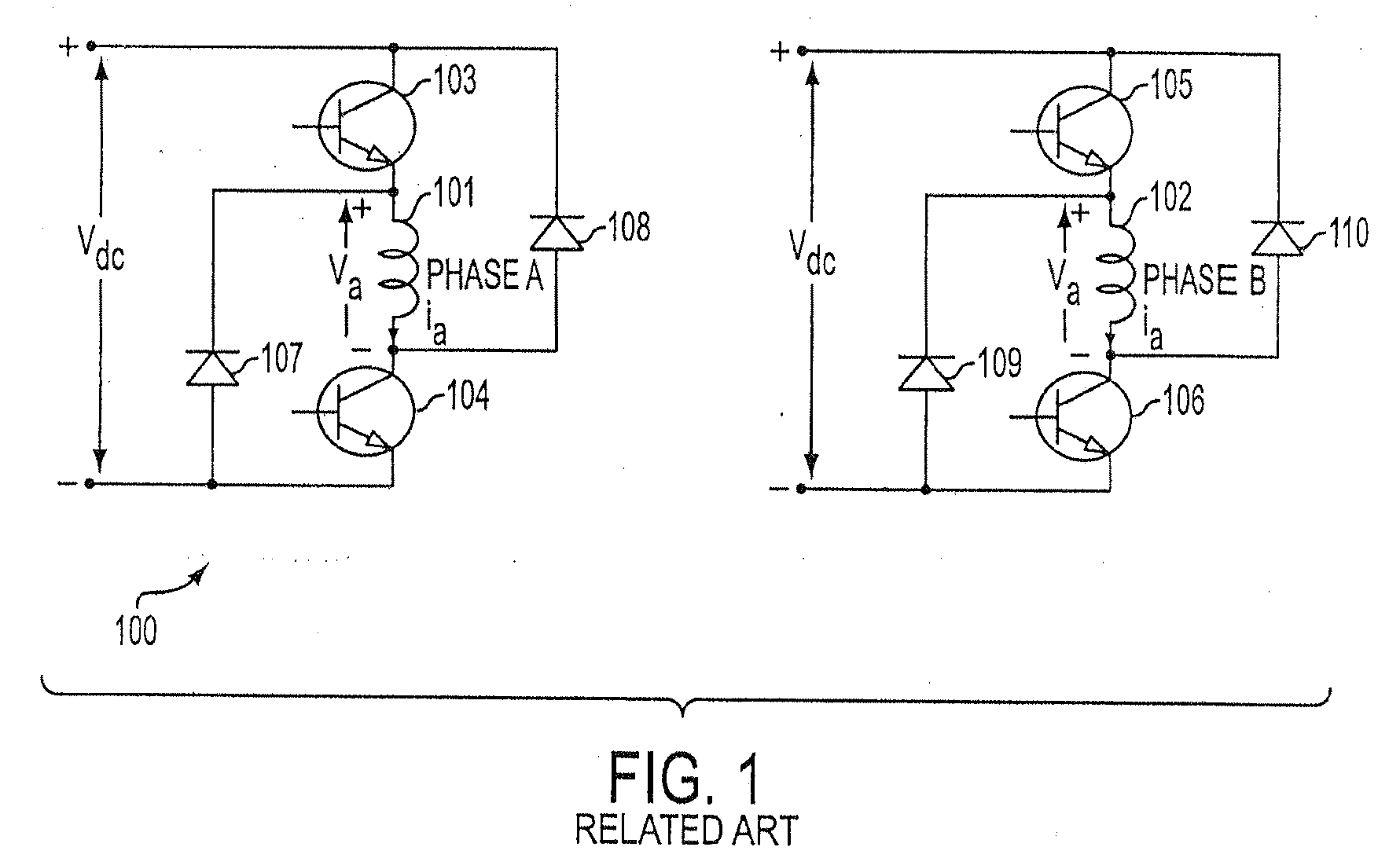
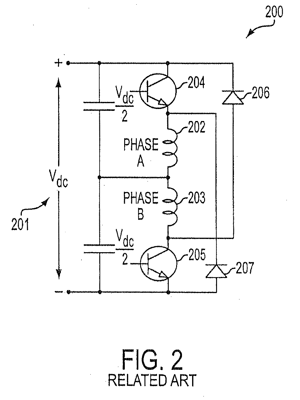
The disadvantage of this power converter topology is that it uses eight power devices.
This results in a circuit requiring one controllable and one uncontrollable power device per phase winding 202, 203.
The disadvantage of this circuit is that it reduces the available dc source voltage by half and, therefore, doubles the current rating required for the devices and for the machine, resulting in low efficiency machine operation.
Use of external inductor 310 increases the cost, whereas the use of the power resistor (not shown) will result in a lower efficiency of the system and higher package volume, due to increased thermal considerations.
Therefore, this circuit is not ideal for use with two-phase SRMs.
This special winding increases the copper volume in the machine windings, resulting in increased cost for the machine.
This leakage inductance can be minimized but cannot be eliminated in a practical machine.
Circuits requiring only two controllable switches and two diodes have the disadvantages of high power loss, low efficiency, and a bifilar winding in the machine, thereby reducing the power density of the machine.
Therefore, existing solutions are not attractive with regard to considerations of high efficiency operation, full range of speed control, compactness in the converter's packaging and, most importantly of all, the overall cost of the system.
A fundamental challenge in power converter development has been to reduce the number of power devices, both controllable and uncontrollable, to a level corresponding to that of a single-quadrant chopper drive, such as is commonly used in a dc motor drive or in a universal motor drive.

Method used


Image

  • Method, apparatus, and system for drive control, power conversion, and start-up control in an srm or pmbdcm drive system
  • Method, apparatus, and system for drive control, power conversion, and start-up control in an srm or pmbdcm drive system
  • Method, apparatus, and system for drive control, power conversion, and start-up control in an srm or pmbdcm drive system

Examples


Embodiment Construction

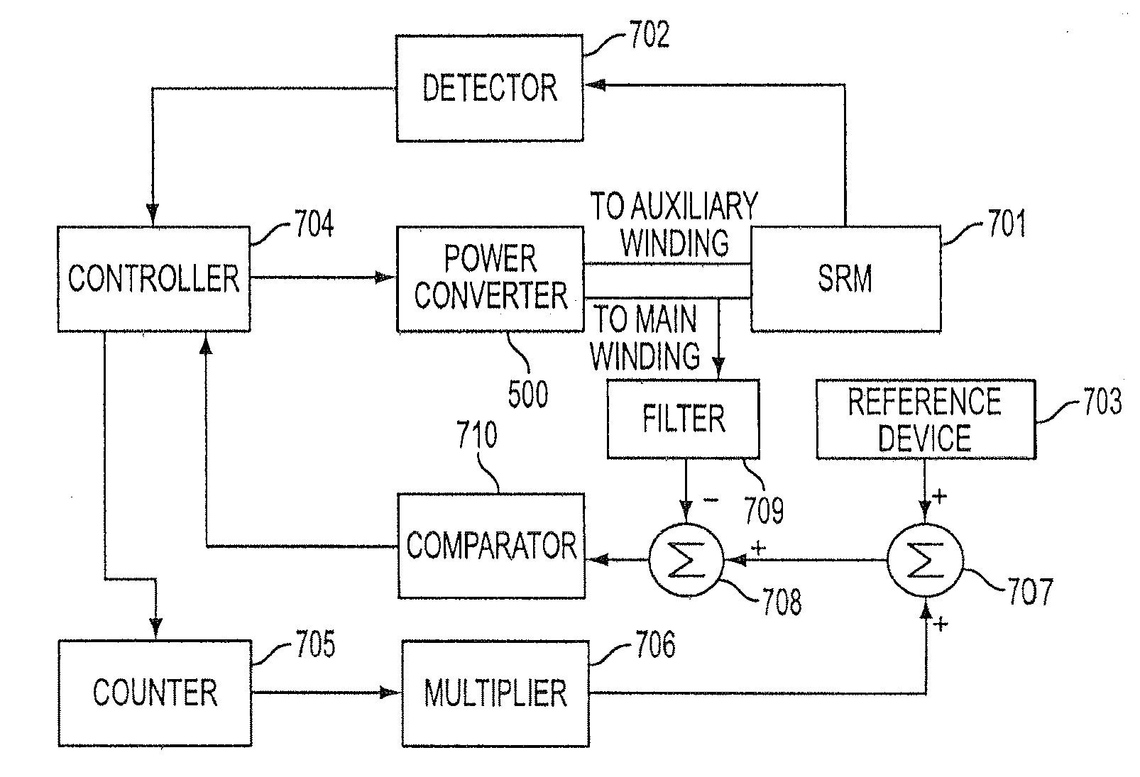
[0050]FIG. 5(a) illustrates a single-switch power controller in the form of converter 500 for driving a two-phase switched reluctance machine (SRM) according to the present invention. One winding of the SRM is alternatively referred to as a main or phase A winding 508, while the other winding is referred to as an auxiliary or phase B winding 505. Although the phase windings 505, 508 of the SRM may be spatially separated from the power converter 500 and may also be considered to form a part of the motor rather than part of the power converter, these windings 505, 508 are illustrated in the power converter circuit for the purpose of simplifying the description of their cooperative functionality with the power converter 500. For this reason, the windings 505, 508 will be illustrated within each embodiment of the power converter 500 described hereinafter.

[0051] When power converter 500 is activated by the application of an ac source voltage 501, a dc source 510 comes into effect throug...


PUM


Abstract

A power converter for a switched reluctance motor or a permanent magnet brushless direct current (dc) motor may include first and second partial circuits for forming multiple conduction circuits in cooperation with first and second phase windings of the motor. The controller also includes a switch operable to open and close a first conduction circuit, which includes the first phase winding, and to regulate energization of the first and second phase windings of the motor through opening and closing the first conduction circuit. Control of the switch provides four-quadrant operation of the motor through regulated energization of the first and second phase windings.

Description

CROSS-REFERENCE TO RELATED APPLICATIONS [0001] This application is a divisional application of Non-Provisional Application Ser. No. 10 / 996,043, filed Nov. 24, 2004, which is a continuation of PCT Application No. PCT / US03 / 16631, filed May 27, 2003, both of which are hereby incorporated in their entireties by reference. This application claims priority to Non-Provisional Application Ser. No. 10 / 996,043, PCT Application No. PCT / US03 / 16631, and to Provisional Application Nos. 60 / 382,608, 60 / 382,609, and 60 / 382,610. Additionally, the application hereby incorporates by reference the disclosures provided in Applicant's Non-Provisional Applications, having Attorney Docket Nos. L1081.03102, L1081.03103, L1081.03104, and L1081.03105.BACKGROUND OF THE INVENTION [0002] 1. Field of the Invention [0003] The present invention relates to a method, an apparatus, and a system for drive control, power conversion, and start-up control in an SRM or a PMBDCM drive system. [0004] 2. Discussion of Related ...

Claims


Application Information

Patent Timeline
Patent Type & Authority Applications(United States)
IPC IPC(8): H02P1/46H02P7/08H02K1/06H02K1/14H02K1/24H02K7/09H02K16/00H02K16/04H02K17/00H02K19/10H02K21/12H02P1/16H02P1/18H02P7/06
CPCH02K1/24H02P2201/09H02K16/00H02K16/04H02K17/00H02K19/103H02K21/12H02M2001/009H02M2003/1552H02M2003/1555H02P1/163H02P1/18H02P6/205H02P25/025H02P25/083H02P25/085H02K7/09H02P6/21H02P25/034H02P25/089H02P25/092H02M1/009H02M3/1552H02M3/1555
Inventor RAMU, KRISHNAN
Owner VIRGINIA TECH INTPROP INC
Learn More