Stenotic device

Active Publication Date: 2007-11-29
LIFE SPINE INC
View PDF11 Cites 13 Cited by
  • Summary
  • Abstract
  • Description
  • Claims
  • Application Information

AI Technical Summary

Benefits of technology

[0015]The present bony spinal protrusion spacer is surgically implanted in a minimally invasive procedure and, as such, may be an inpatient procedure. Moreover, the implantation procedure typically takes less than one hour to perform and allows patients to walk out of the surgical locale (e.g. hospital) the same day due to rapid recovery and minimal risk of systemic and local complications.
[0016]Unlike decompressive surgery/laminectomy, the procedure for implanting the present spinal spacer is completely reversible, leaving all anatomical structures intact. Thus, the implantation procedure for the present spinal spacer can be used as a first line surgical approach without compromising any th

Problems solved by technology

Such degenerative or age-related changes in our bodies can lead to compression of nerves (i.e. pressure on the nerves that can cause pain and/or damage).
Lack of activity because of lumbar spinal stenosis may lead to obesity, depression and general physical deterioration.
Such non-surgical treatments do not correct the spinal can

Method used


Image

  • Stenotic device
  • Stenotic device
  • Stenotic device

Examples


Embodiment Construction

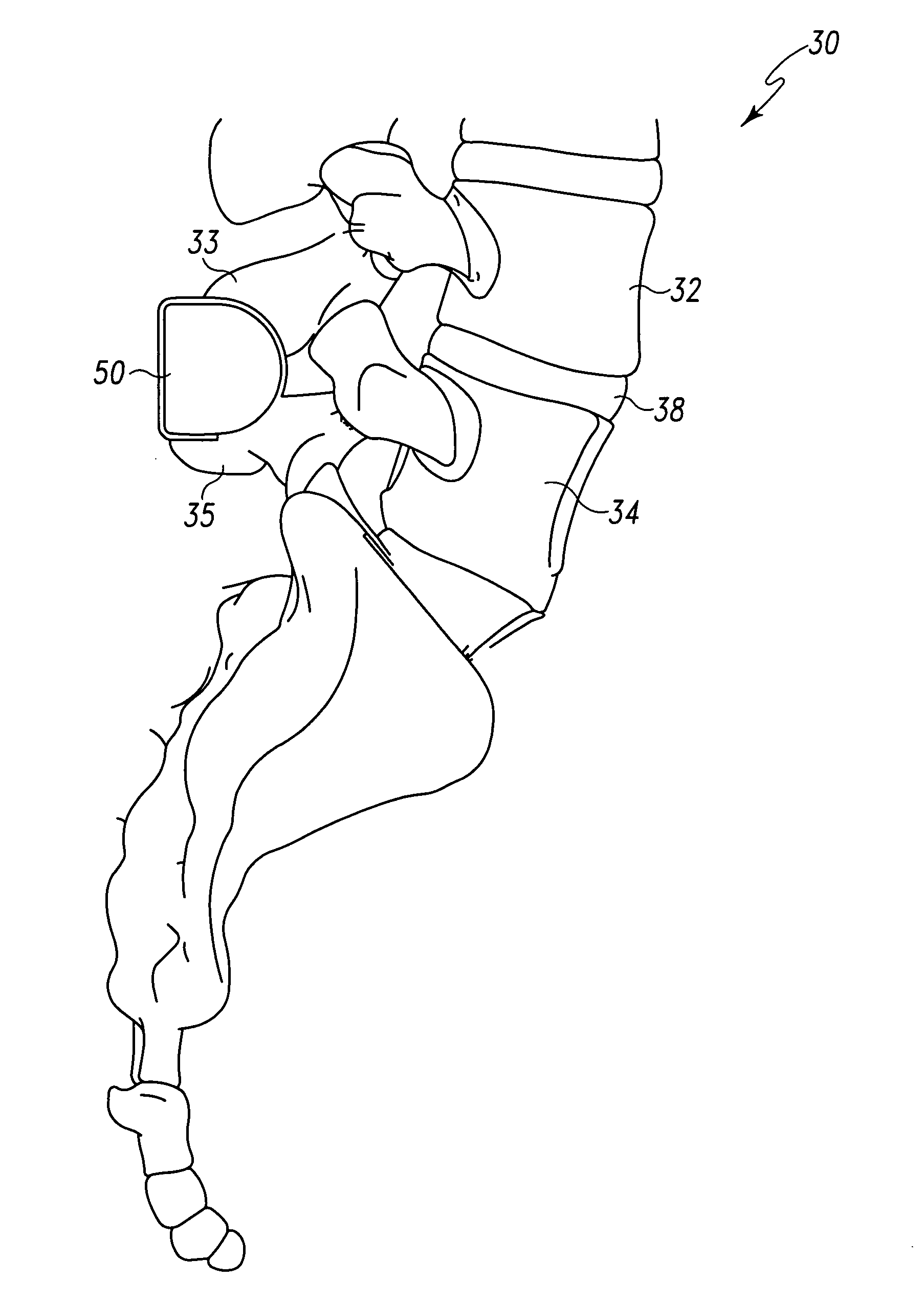
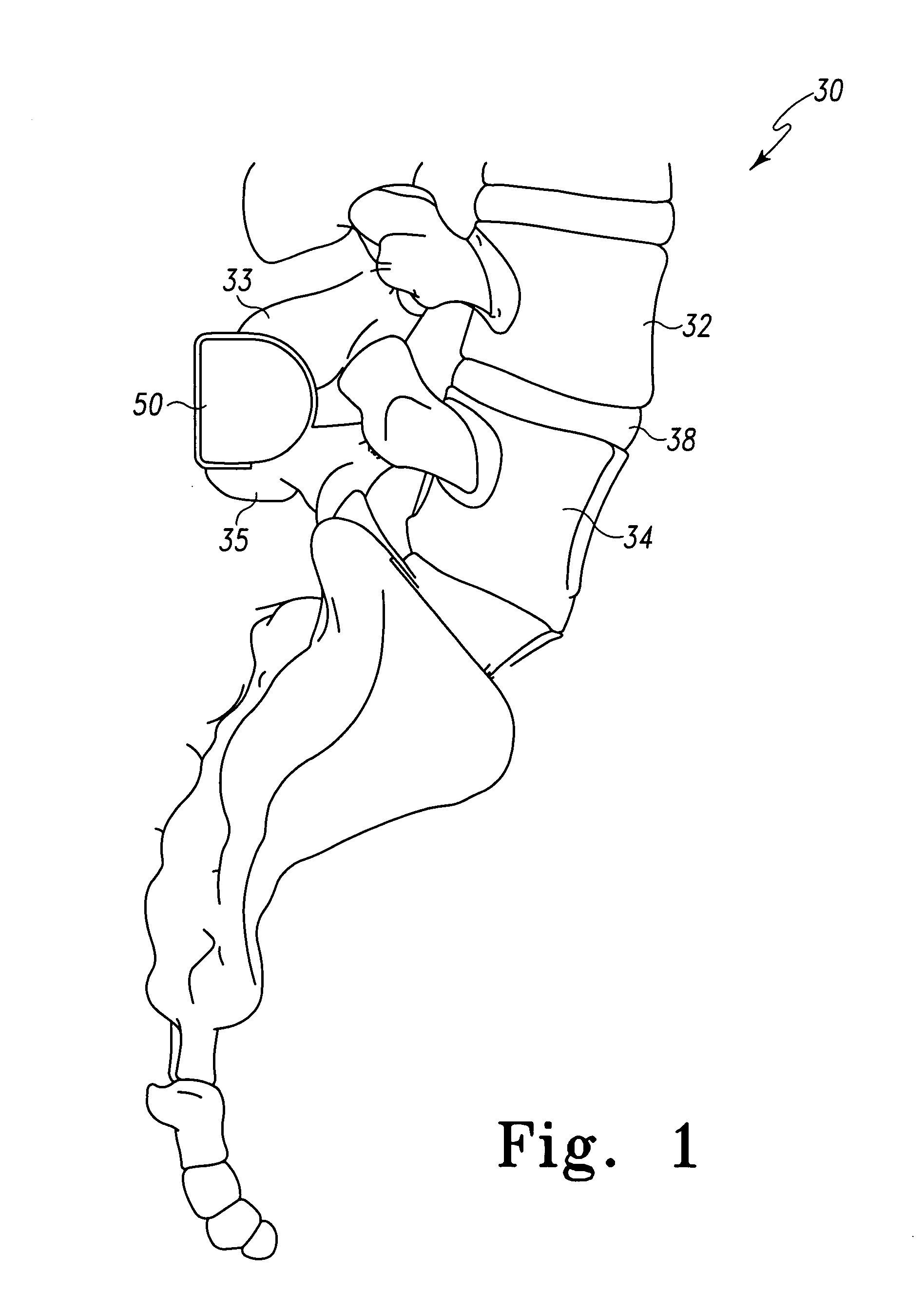
[0042]FIG. 1 depicts the lumber region 30 of a human spine. A bony spinal protrusion spacer, spinous process spacer, interlaminar spacer, or inter-joint spacer spinous process spacer 50, representing all embodiments of a bony spinal protrusion spacer according to the principles presented herein, is shown situated between the spinous processes 33 and 35 of respective adjacent vertebrae 32 and 34. A disc 38 is naturally disposed between the vertebrae 32, 34. It should be appreciated that while the present bony spinal protrusion spacer 50 is shown situated between spinal processes 33 and 35, the present bony spinal protrusion spacer 50 may be used as an interlaminar, interbody, or interbony spinal protrusion spacer. As such, while the present bony spinal protrusion spacer 50 is shown and described in relation to the spinal processes of adjacent vertebrae, the bony spinal protrusion spacer may be used as an interlaminar, interbody or interbony spinal protrusion spacer and the principles...


PUM


Abstract

A spinal implant is configured to be received between bony spinal protrusions of adjacent vertebrae particularly, but not necessarily, in the lumbar region of the spine and hold them apart. The spinal implant may be used interlaminar, interbody or interbony protrusion. The present bony spinal protrusion spacer is not fixed to any bony structures of the vertebrae and, as such, use of the present bony spinal protrusion spacer does not result in fusion. It may therefore be removed if necessary. Attachment structures formed as part of the bony spinal protrusion spacer receive and engage portions of adjacent bony protrusions. The attachment structures provide one or more ridges, bumps, protrusions, projections, lips, flanges, overhangs, overhangs that are threadably engaged, extensions and/or the like that form one or more pockets or cavities into which portions of adjacent bony spinal protrusions are separately lodged and held. In this manner (via retention of the bony spinal protrusions), appropriate and/or desired spacing between adjacent vertebrae is maintained. As such, the present bony spinal protrusion spacer is designed to remain safely and permanently in place without attaching to the bone or ligaments of the back.

Description

RELATED APPLICATIONS[0001]This patent application claims the benefit of and / or priority to U.S. Provisional Patent Application No. 60 / 798,894 filed May 9, 2006, entitled “Interspinous Process Spacer” the entire contents of which is specifically incorporated herein by reference.BACKGROUND OF THE INVENTION[0002]1. Field of the Invention[0003]The present invention relates to devices for the spine and, more particularly, to a spinal implant for the treatment of stenotic spinal bone.[0004]2. Background Information[0005]As we age various changes can occur in the body. For instance, the ligaments of the spine can thicken and calcify (i.e. harden from deposits of calcium), bone and joints may enlarge, bone spurs called osteophytes may form, spinal discs may collapse and bulge (i.e. herniate) or one vertebra may slip over another (spondylolisthesis). Any one or these conditions and / or others can cause what is known as lumbar spinal stenosis. Lumbar spinal stenosis is a narrowing of the bony ...

Claims


Application Information

Patent Timeline
IPC IPC(8): A61F2/30
CPCA61B17/7062A61B17/70
Inventor BUTLER, MICHAEL S.MILELLA, MICHAEL J.
Owner LIFE SPINE INC
Why Eureka
Try Eureka