
Laterally Curved Surgical Clip

a laparoscopic and surgical technology, applied in the field of laparoscopic surgical clips, can solve the problems of loss of patients and limitations of electronic equipment (electromedicine)

Inactive Publication Date: 2007-11-29
MENDES JR JOSE BARBOSA +1
View PDF12 Cites 191 Cited by
  • Summary
  • Abstract
  • Description
  • Claims
  • Application Information

AI Technical Summary

Benefits of technology

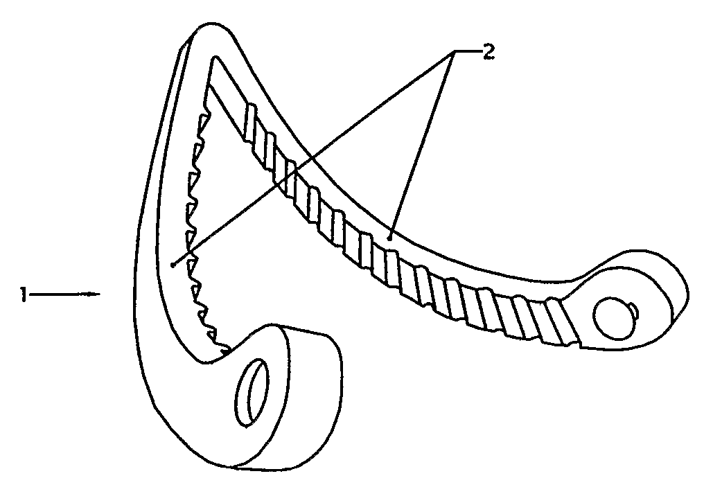
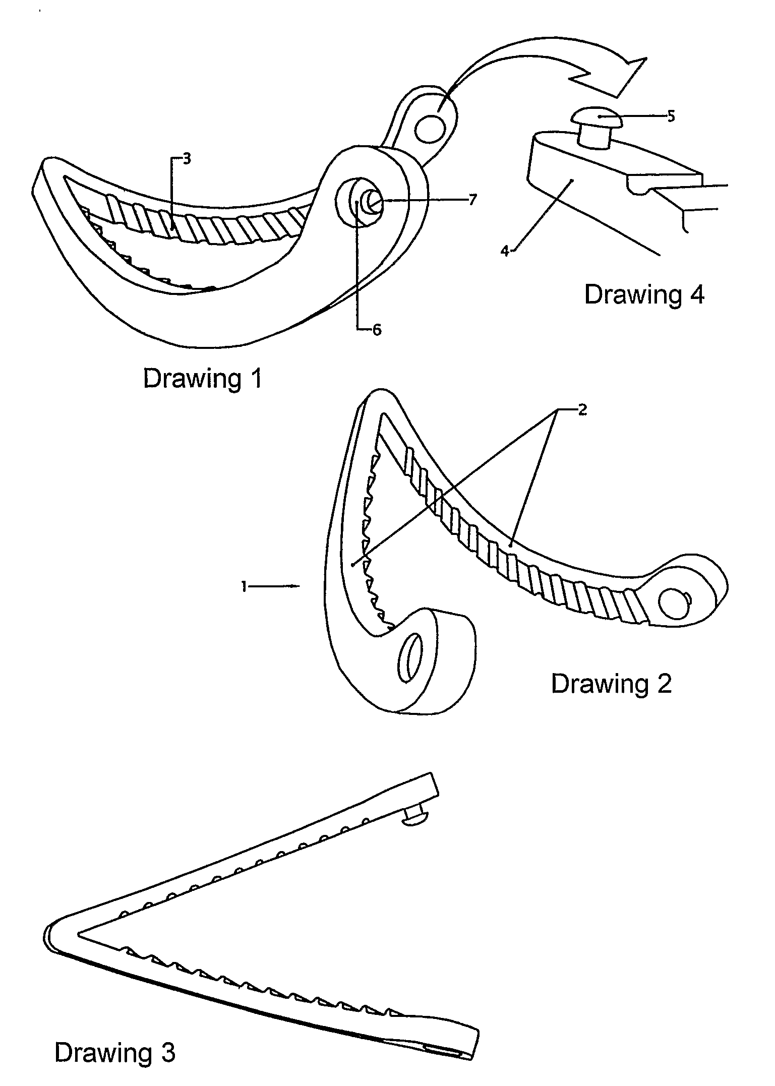
[0001] This utility model patent report describes a Laterally Curved Laparoscopic Surgical Clip, which is a self-locking surgical instrument. It is used in surgeries where vascular occlusion, or the occlusion of other structures is needed. Since it has an innovative curved lateral design it not only provides for secure stanching of the vessels and structures but also has a self-locking male-to-female system, while allowing for the viewing of the entire clip extension making it possible to leave the locking mechanism away from the clipped area. Altogether, this makes up for great improvements when compared to the existing linear designed clips. INTRODUCTION
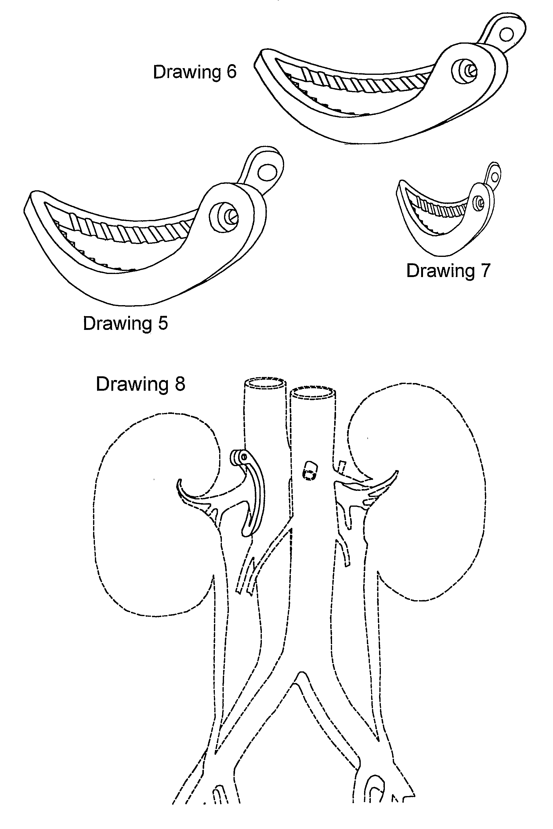
[0008] The surgical apparatus hereby presented is based on a technical, surgical fundament of the classic utilization of curvature in the majority of surgical instruments that are employed for the dissection of organs and vascular structures. This design has been conceived with the intent to incorporate these fundaments to the usage of clips and it constitutes an innovative improvement for their use and application. Therefore, it is the first laterally curved conceived device, self-locking, or not. Since it allows for lateral and partial applications on large vessels or other structures, the lateral curvature provides the clip with advantages over the straight ones. Due to its curved shape, this clip has two working surfaces: an effective one, which is meant to be used with vascular occlusion, and a non-effective one, which is used with the locking system, thus avoiding the clipped vascular structure. Another advantage of its curved shape is based on the surgeon's better visualization of the clip locking end, thus avoiding undesirable inclusions of tissues or perivascular structures. Therefore, since it is possible to view the entire length of the clip, it allows for secure sectioning of the vessel, i.e., the faces of the occlusion where the lateral grooves and protrusions are located are both coplanar or flat in relation to each other, although curved in relation to its major view axis (front), thus allowing for partial capturing of the wall in a large vessel. It leaves its locking portion away from the structure being worked on, and doesn't perforate, tear and / or cause any lesion to it.
[0009] The locking system on this curved clip is based on a “male-to-female” type, and is incorporated in the clip's free end, where a mushroom-shaped pin can, under pressure, be adjusted to an orifice. Both the “male” and “female” parts are placed in the central part of the free end. Once it is locked in place, this clip does not present any risk of spontaneous or accidental opening. This locking system is designed to facilitate the manufacturing and the operation of the device. In order to lock it, pressure is exerted along one direction only of the applicator, thus eliminating the need to displace one leg over the other in order to lock it in place. Moreover, such applicator should be able to rotate 360° around its distal end, in order to allow for the same curved clip to be applied both to the left and to the right.
[0010] In order to provide this device with a lower risk of slippage from the clipped vessel wall, there are grooves and transversal protrusions that self adjust, therefore providing the device with an additional locking mechanism for the structures.
[0011] There is a technical variant of this system, which is incorporated along the occlusion face of the clip and is based on the longitudinal disposition of grooves along one of the legs and protrusions along the opposite leg. These also self adjust, and the purpose is again to provide a better grip of the structures.

Problems solved by technology

That is why unexpected surgical problems during the operation are the most frequent causes of conversions to open surgery or even loss of patient.
Despite its practicality and speed, the use of electronic equipment (electromedicine) faces some limitations when it comes to working with large vessels or when one considers the operational cost.

Method used


Image

  • Laterally Curved Surgical Clip
  • Laterally Curved Surgical Clip
  • Laterally Curved Surgical Clip

Examples


Embodiment Construction

OF APPLICATIONS

[0014] Within urology, for example, the anatomy of kidneys presents the following particularities:

[0015] The right kidney vein is rather short, and since the vena cava is located at the right of the aorta, the nephrectomy of a live donor for transplantation is preferably done at the left side, thus enabling the extraction of a venous segment which is long enough to be worked on. The importance of the length of this vein is that the venous reconstruction is done through a terminal-lateral anastomosis, thus, if we are working with a short vein segment this anastomosis will offer some technical difficulties as well as complication risks due to obstruction by thrombosis. This happens due to an imperfect suture or to stretching of anastomosed vessels. Considering that the surgery of the donor presents unique characteristics when it comes to surgical risks, for it deals with an individual who does not present any pathology and is being submitted to a major surgery, the sta...


PUM


Abstract

This invention is a self-locking, surgical instrument designed to be utilized in surgical procedures where total and / or partial vascular occlusion of large blood vessels, or other structures, is needed, thus providing secure stanching of the vessels and structures due to its curved lateral design. This innovative design not only allows for a clear view of the entire extension of the clip, but also has a “male-to -female” self-locking system, which stays clear of the area being clipped, thus constituting an improvement upon the existing traditional straight clips.

Description

PRESENTATION [0001] This utility model patent report describes a Laterally Curved Laparoscopic Surgical Clip, which is a self-locking surgical instrument. It is used in surgeries where vascular occlusion, or the occlusion of other structures is needed. Since it has an innovative curved lateral design it not only provides for secure stanching of the vessels and structures but also has a self-locking male-to-female system, while allowing for the viewing of the entire clip extension making it possible to leave the locking mechanism away from the clipped area. Altogether, this makes up for great improvements when compared to the existing linear designed clips. INTRODUCTION [0002] Laparoscopic surgery is a surgical modality which is well established in several surgical areas, from extirpative to reconstructive procedures. Due to the fact that it is a minimally invasive modality of surgery, it has been considered as the “gold standard” for some procedures. For that reason, laparoscopic su...

Claims


Application Information

Patent Timeline
Patent Type & Authority Applications(United States)
IPC IPC(8): A61B17/08A61B17/064
CPCA61B2017/00809A61B17/122
Inventor MENDES JR, JOSE BARBOSATANAKA, MILTON TATSUO
Owner MENDES JR JOSE BARBOSA
Learn More