
Centrifugal Fluid Filtration Devices, Systems and Methods

a centrifugal fluid and filtration device technology, applied in centrifuges, separation processes, filtration separation, etc., can solve the problems of increasing energy dilemma, salt water, and requiring an expensive and energy-intensive desalination process, so as to reduce the cost, less space, and less time

Inactive Publication Date: 2007-12-06
FILTRATION DYNAMICS
View PDF62 Cites 5 Cited by
  • Summary
  • Abstract
  • Description
  • Claims
  • Application Information

AI Technical Summary

Benefits of technology

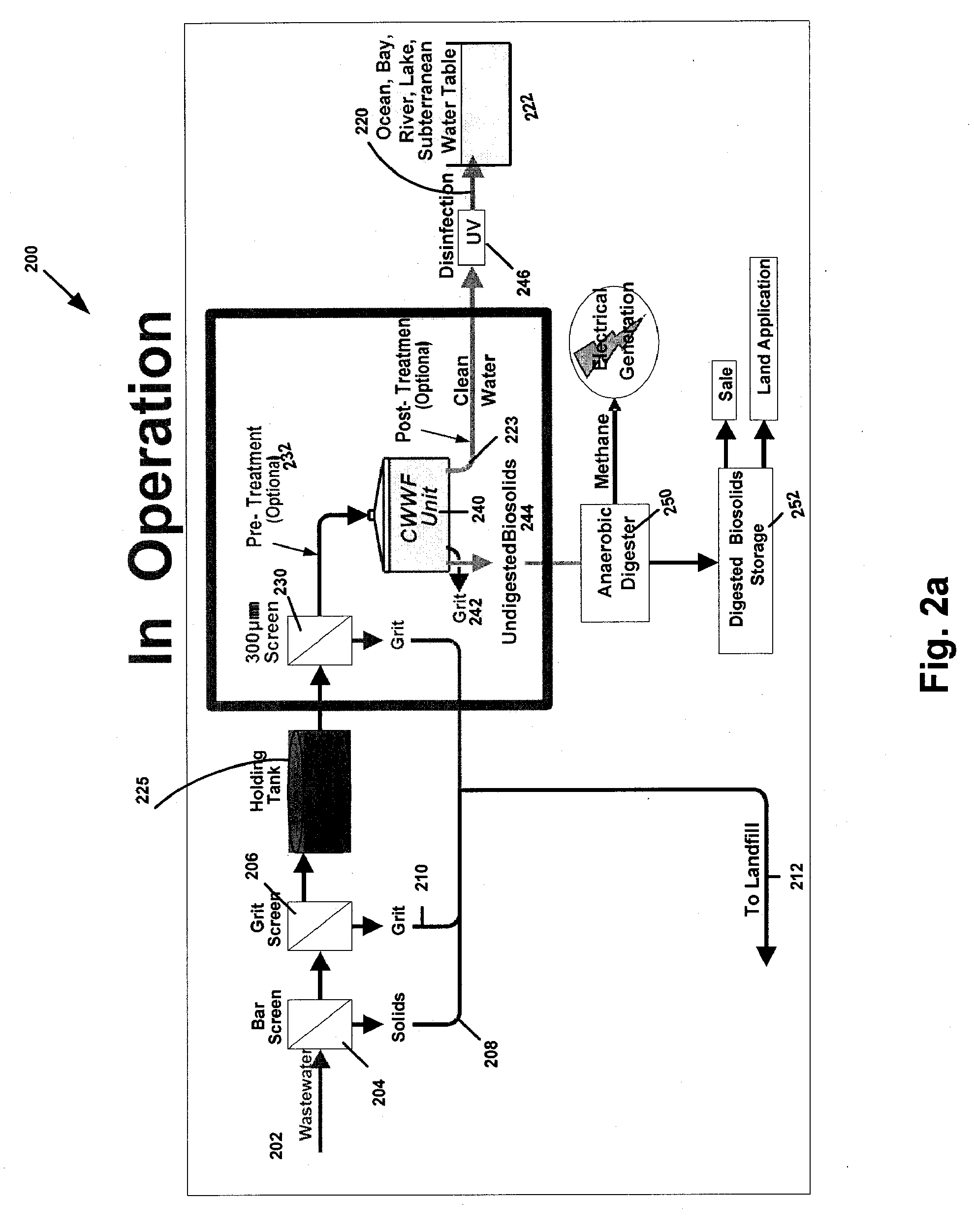
[0010]An object of the invention is directed to a solution for wastewater treatment which is scaleable, volume adjustable and employs centrifugal fluid filtration. Furthermore, the devices, systems and methods eliminate five separate operations typically performed in wastewater treatment which will enable the device, systems and method of the invention to operate in less time and in less space, at lower cost, while consuming less than one-third the electricity used to process the same amount of wastewater using current solutions.
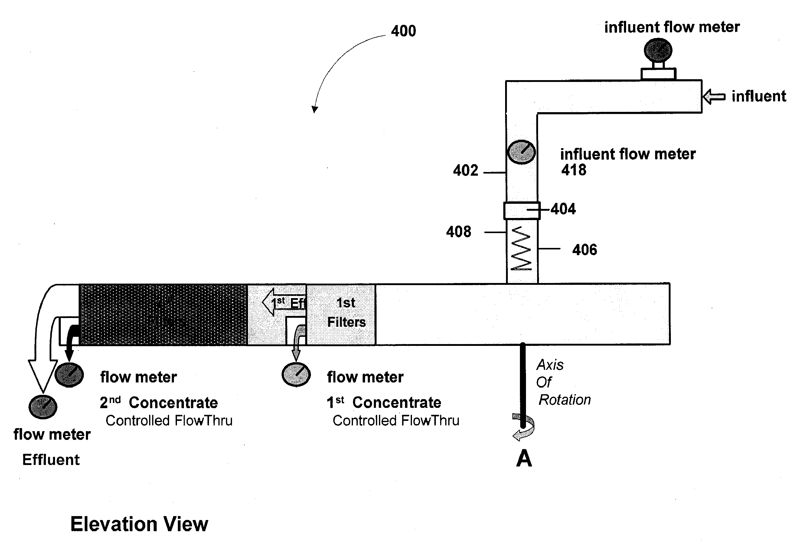
[0013]Yet another aspect of the invention provides for a radial arm / filter unit that has filters attached to each arm in series or parallel. The influent conduits of the radial arm enhance the Coriolis forces on the influent across the membrane medium.
[0016]Another aspect of the invention is directed to a fluid filtration device comprising: an influent feed tube; an influent receiving bowl in fluid communication with the influent feed tube; a plurality of radial arms having filters therein configured to rotate about an axis within the influent receiving bowl; and one or more vanes which increase an efficiency with which fluid is transferred through the filtration device.
[0021]A plurality of radial arms can be two or more, multiples of two or multiples of three in any of the designs. Additionally, a controller can be provided for controlling a rate at which the radial arms rotate about the axis. Moreover, one or more vanes can be positioned within one or more of the influent feed tube and radial arms to control the speed and direction of travel of the influent. The vanes can be optimally configured to enhance a Coriolis effect on the influent which has an antifouling effect as the influent crosses the filters disposed within the radial arms. In some configurations, an anaerobic digester can be provided that is in communication with the fluid filtration device. The anaerobic digester can, for example, generate methane from an undigested biosolids it receives from the fluid filtration device. Furthermore, a disinfector can be provided for disinfecting a filtered fluid effluent prior to emission, such as prior to emission to an external water supply such as an ocean, bay, river, stream, lake or subterranean water table. One or more sensors can be provided to communicate a sensed parameter to a controller.

Problems solved by technology

Salt water, which represents the vast majority of water, requires an expensive and energy intense desalination process before it is can be used for drinking.
In addition to a limited access to fresh water, we face an increasing dilemma related to energy.
However, the systems are still quite large.
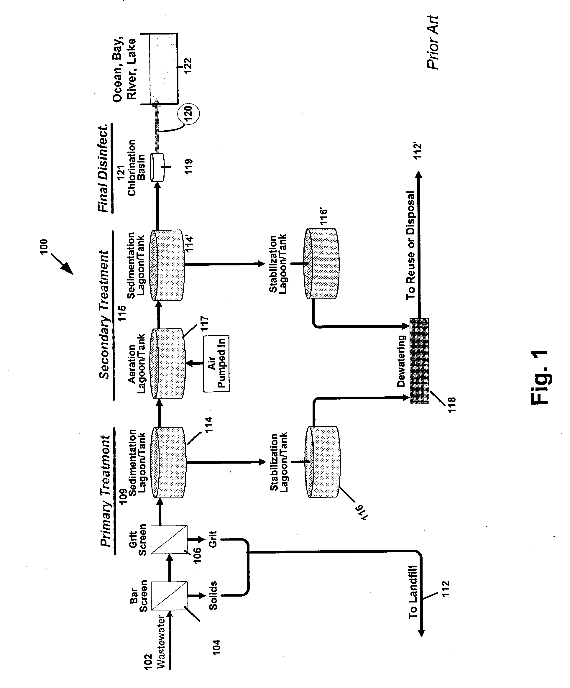
Currently there are several important issues facing the design of current wastewater treatment facilities for which there has been an insufficient solution.
First, most wastewater treatment facilities consume a significant amount of energy during operation.
Second, wastewater treatment facilities typically require a substantial amount of land.
Third, wastewater treatment facilities often emit an unpleasant odor which can make them undesirable to place strategically in an urban setting, notwithstanding the space requirements.
Fourth, wastewater treatment facilities present a potential security risk because the facilities are part of a critical infrastructure that must be protected to ensure an adequate supply of water.

Method used


Image

  • Centrifugal Fluid Filtration Devices, Systems and Methods
  • Centrifugal Fluid Filtration Devices, Systems and Methods
  • Centrifugal Fluid Filtration Devices, Systems and Methods

Examples


Embodiment Construction

[0039]For purposes of illustration of the concepts of the invention, the various features are discussed with respect to wastewater treatment. However, those skilled in the art will appreciate that the teachings can be applied to other industries such as pharmaceutical and food processing. Commercial applications for this invention are numerous and include, but are not limited to: drinking water and wastewater treatment for municipalities; non-community wastewater systems and housing developments; and wastewater treatment for commercial business developments, condominiums, malls, hotels / motels, office buildings, hospitals, resorts, and government and military installations. Additional applications may include, but are not limited to, isolation, separation, purification, removal, recovery, and / or concentration of biological components in the pharmaceutical and biotechnology industries. The device may also be used for water clean-up in power plants; and water and wastewater clean-up in...


PUM

PropertyMeasurementUnit
speedaaaaaaaaaa
antifouling effectaaaaaaaaaa
energyaaaaaaaaaa

Abstract

Fluid filtration devices, systems and methods are disclosed. The device comprises, for example, an influent feed tube; an influent receiving bowl in fluid communication with the influent feed tube; and a plurality of radial arms having filters therein configured to rotate about an axis within the influent receiving bowl. The fluid filtration devices, which can be configured to filter a wide variety of fluids, comprises: an influent feed tube; an influent receiving bowl in fluid communication with the influent feed tube; and a plurality of radial arms having filters therein configured to rotate about an axis within the influent receiving bowl. Additionally, methods are provided for that comprise, for example: obtaining an influent from a target source of fluid to be filtered; filtering the influent in a first filtration step; filtering the influent in a second filtration step upon receiving effluent from the first filtration step by transferring influent through a plurality of radial arms by rotating the radial arms having filters disposed therein about an axis in a filtration unit; and emitting a final filtered fluid effluent.

Description

CROSS-REFERENCE[0001]This application claims the benefit of U.S. Provisional Application No. 60 / 803,614, filed May 31, 2006 and 60 / 803,616 filed May 31, 2006 which are incorporated herein by reference in its entirety.BACKGROUND OF THE INVENTION[0002]It has been said that “water is the oil of the 21st century” because of its huge demand and finite supply. Although it is estimated that greater than 75% of the earth's surface is covered by water, only a very small fraction of that water is drinkable or usable without treatment. Over 96% of water is ocean, seas and bays. Of fresh water, nearly 70% is trapped in ice caps, glaciers and permanent snow. (See, www.earthobservatory.nasa.gov). Salt water, which represents the vast majority of water, requires an expensive and energy intense desalination process before it is can be used for drinking.[0003]The U.S. has more than 97,000 water treatment facilities. The projected annual growth rate for water treatment is 5%-8% over the next decade. ...

Claims


Application Information

Patent Timeline
Patent Type & Authority Applications(United States)
IPC IPC(8): B01D33/00
CPCB04B3/00B04B5/10C02F1/004C02F1/32C02F1/38C02F1/76Y02E50/343C02F11/04C02F2103/007C02F2103/06C02F2103/08C02F2303/04C02F5/00Y02E50/30
Inventor COOK, MELVIN W.
Owner FILTRATION DYNAMICS
Learn More