
Audio equipment storage device

a technology for audio equipment and storage devices, applied in the direction of movable shelf cabinets, dismountable cabinets, folding cabinets, etc., can solve the problems of reducing the quality of listening or viewing experience for individuals, causing primary sources of vibration in audio equipment, and affecting the listening or viewing experience of individuals, so as to reduce, ameliorate, or eliminate the deleterious effects

Inactive Publication Date: 2007-12-06
WIEBE JOHN
View PDF20 Cites 26 Cited by
  • Summary
  • Abstract
  • Description
  • Claims
  • Application Information

AI Technical Summary

Benefits of technology

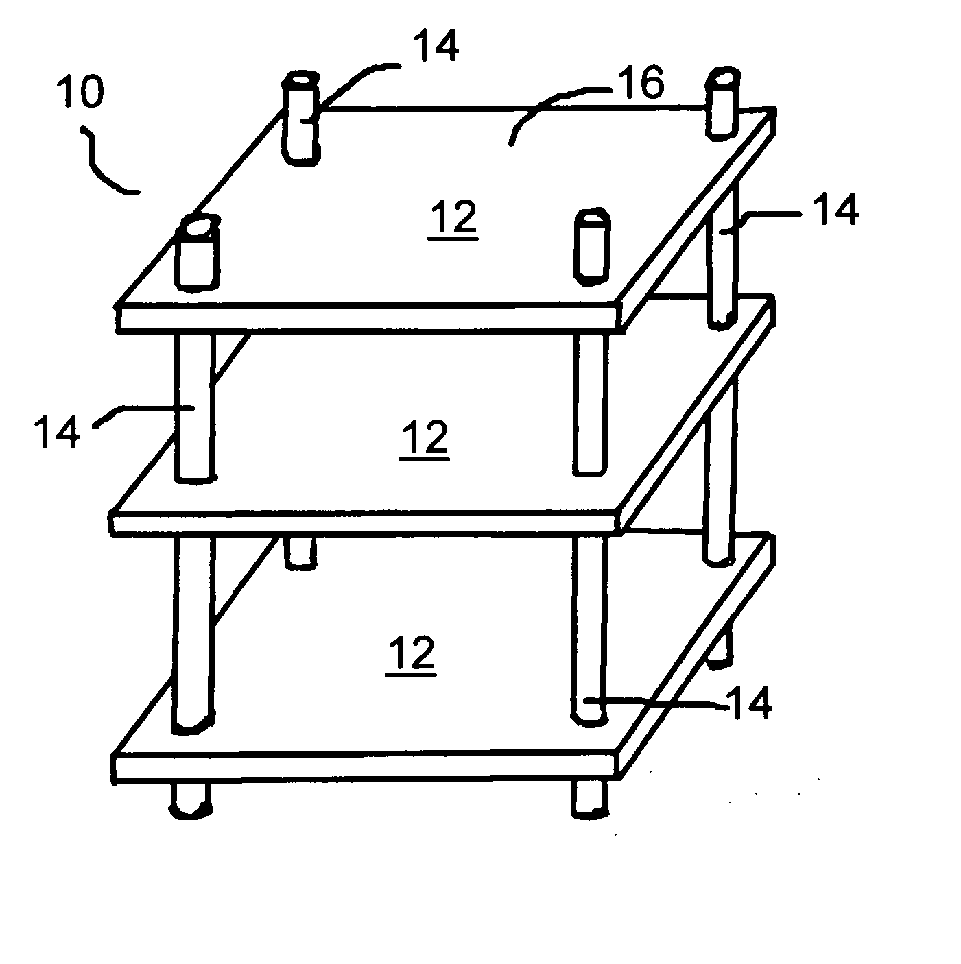
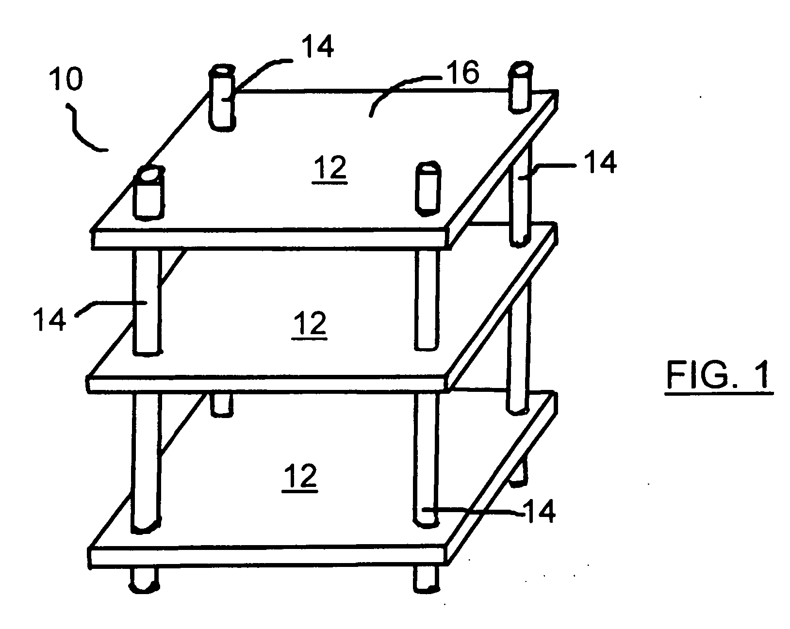
[0015] With the above problems and limitations of the known art in mind, the present invention was developed with the goals of providing a vibration isolating device which inherently provided in the cabinet or support shelf on which the vibration equipment rests, so as reduce, ameliorate, or eliminate the deleterious effects caused by vibration in vibration sensitive equipment. It is further among the advantages of the present invention that the new vibration reduction devices be suitable for manufacture in a variety of sizes or models so as to be capable of handling various sizes of loads and a variety of applications.
[0023] In particular, the shelf support device of the present invention is provided with at least one surface or composition feature which attenuates the vibration which is ultimately resonant in the shelf structure. Commonly, prior art shelf support devices are made of a materials such as wood, or tubular aluminum, tubular steel or the like, which can aid in the transmission of any vibration to the shelf. The shelf support device of the present invention is preferably made of a vibration absorbing material or a vibration dispersive material. A preferred vibration absorbing material is a composite fiber material, and most preferably, a hollow tube which has been fabricated from a carbon fibre material. A vibration dispersive material is a solid metallic rod, and most preferably, a solid aluminium rod, which acts to cause increased radial dispersion of the vibration within the support and thus, less propagation of the vibration along the support.

Problems solved by technology

One of the main causes of such performance variations in such equipment is vibration, particularly that which is referred to as “micro” vibration within the audio equipment, such as with compact disk (“CD”) players, preamplifiers, amplifiers, phonograph stages, and turntables.
A primary source of vibration in audio equipment is caused by the sound waves generated by the audio equipment, particularly if the equipment is operated at louder volumes, or repeatedly generates audio frequencies at selected harmonic frequencies.
Other, “macro” vibrations may also happen when a door is slammed, the equipment is bumped, or even from floor movement caused by a person walking in the room.
The irregularities in sound or visual quality of the product caused by the vibration are very distracting to the experienced observer significantly decrease the quality of the listening or viewing experience for these individuals.
Similarly high technology and laboratory equipment such as microscopes, scales, etc. may likewise be negatively affected by vibrations, even to the extent of causing data produced or collected thereon to be unreliable.
However, each of these different methods has certain limitations or disadvantages.
Some of the known methods, such as air isolation devices and some seismic sinks are quite expensive and also require a source of pressurized air.
Vibration absorbing materials are limited in the capability to attenuate vibration.
Spikes and cones “drain” vibration to the ground or other support surface, rather than actually isolating the performance device from the vibration; and sand boxes, by definition, include the use of sand, which can be very messy and necessarily creates the risk of inadvertent introduction of sand particles and dust into expensive performance equipment, accessories, tapes, compact disks, and anything else in the vicinity of use of the sand.
However, little has been done in the area of providing a shelf structure or cabinet structure which aids in the reduction of vibration.

Method used


Image

  • Audio equipment storage device
  • Audio equipment storage device
  • Audio equipment storage device

Examples


examples

[0067] A series of support configurations were tested to evaluate the propagation of vibration within the stand.

Testing Parameters

[0068] Since every electronic component used for the subjective listening tests was receiving a 60 Hz, 117 V electrical input, the test frequencies chosen were multiples of 60 Hz. As such, the test frequencies used were 60 Hz, 120 Hz, 240 Hz, 600 Hz, 1200 Hz, 3000 Hz, and 6000 Hz.

[0069] To increase the likelihood of finding significant differences in vibration response between different test racks, instead of merely varying the input AC frequency, a loudspeaker was placed on the top shelf, with the drivers facing directly downward. This loudspeaker (System-Audio S2K) consisted of a tweeter and a mid-bass driver. It was supported by a two-piece stabilizing cone / spike on each corner. The location of each cone / spike was consistent for each test rack configuration. As a result, both acoustic vibrations and direct mechanical vibrations from the loudspeaker...


PUM


Abstract

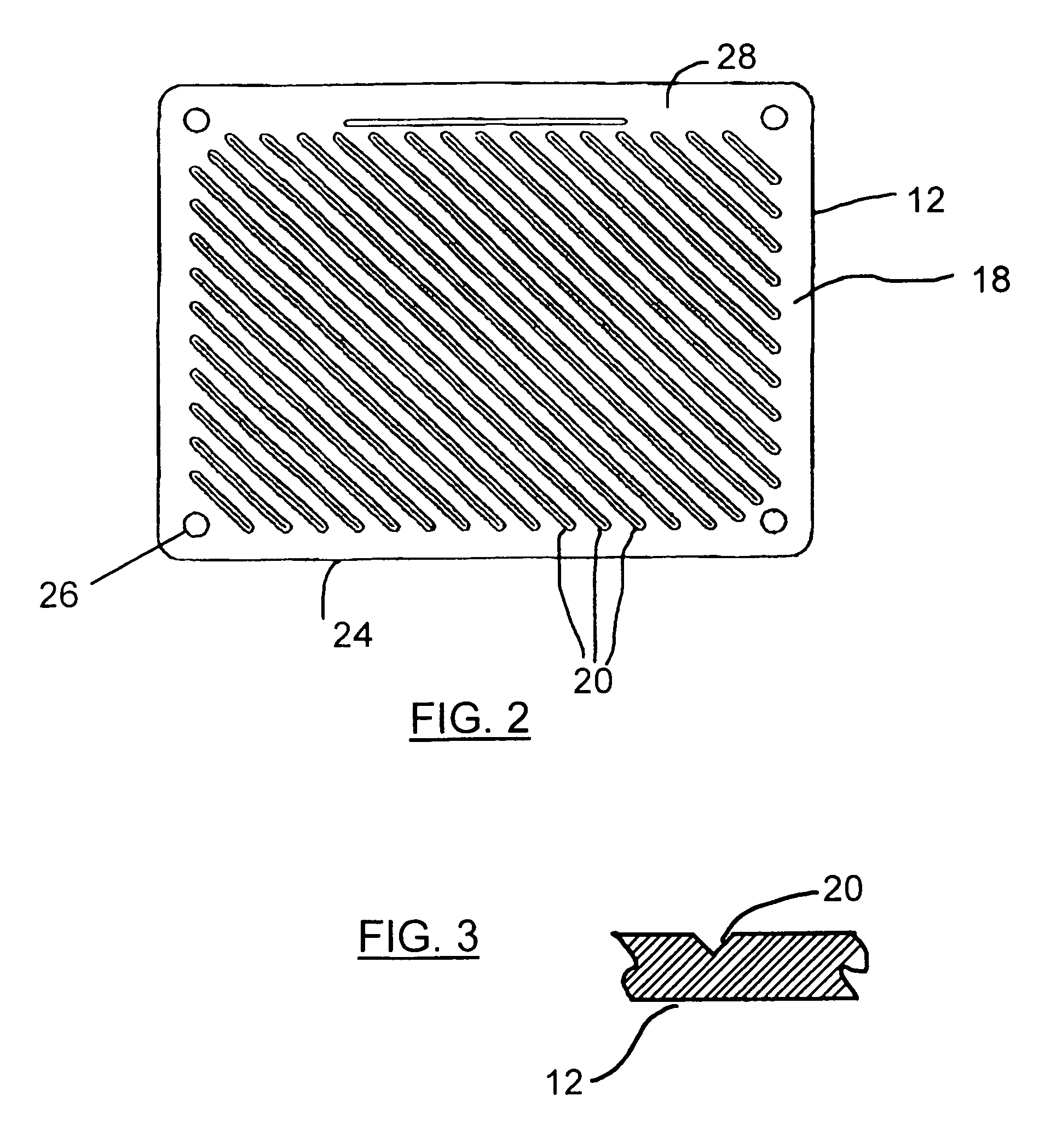
Modifications to the structural elements of racks / shelves for component shelves, and in particular, audio components are provided in order to improve the sound produced by the system by minimizing the effects of vibration on the equipment positioned on the shelves. In particular, adding a series of grooves to the lower surface of each shelf was found to be of assistance in attenuating the vibration measured on the shelf surface. Additionally, using vertical supports manufactured of a tube of a composite fibre material, such as a carbon fibre / graphite reinforced plastic (GRP) or a solid metallatic support, such as a support made of an aluminum rod, was also found to attenuate the vibrations measured on the shelf surface. As such, a method and device for ameliorating the effects of vibration on vibration sensitive equipment is provided.

Description

FIELD OF THE INVENTION [0001] The present invention relates generally to the field of vibration isolation mechanisms in a shelving unit or cabinet, and, more particularly, to vibration control devices which provide improved inherent vibration control in a shelving unit or cabinet in an economical fashion. The shelving unit or cabinet is well suited for use with, for example, audio equipment or other vibration sensitive equipment. BACKGROUND OF THE INVENTION [0002] People who spend a significant amount of time listening to music often become particularly astute to hearing extraneous variations, which can be caused by a number of factors. One of the main causes of such performance variations in such equipment is vibration, particularly that which is referred to as “micro” vibration within the audio equipment, such as with compact disk (“CD”) players, preamplifiers, amplifiers, phonograph stages, and turntables. [0003] A primary source of vibration in audio equipment is caused by the s...

Claims


Application Information

Patent Timeline
Patent Type & Authority Applications(United States)
IPC IPC(8): A47B57/00
CPCA47B87/0223
Inventor WIEBE, JOHN
Owner WIEBE JOHN
Learn More