Slotted high lift aerofoils

a high-lift, aerofoil technology, applied in aircraft control, wing adjustment, aircraft components, etc., can solve the problems of reducing the operation in an otherwise allowable part of the flight envelope, stalling of the wings, loss of the aerodynamically generated controlling force of the aileron, etc., to reduce the angle of attack, reduce the speed safety margin, and increase the lift

Active Publication Date: 2007-12-06
ISRAEL AEROSPACE IND
View PDF2 Cites 15 Cited by
  • Summary
  • Abstract
  • Description
  • Claims
  • Application Information

AI Technical Summary

Benefits of technology

[0053]Elimination of speed safety margin is possible, post-stall flight capabilities and “passive self-recovery in pitch plane” may be provided in some embodiments. In other words, the increased moment arm due to upstream migration of the center of lift when flow separation occurs, coupled with possibly increased lift at the tail, can provide a restoring moment to the air vehicle in the pitch plane, thereby tending to reduce the angle of attack in a passive manner.

Problems solved by technology

However, this practice also results in a restriction in the operation of the air vehicle, particularly UAV's, to above a specified airspeed (which includes a speed safety margin imposed on stall airspeed), reducing operation in an otherwise allowable part of the flight envelope.
For such cases, reducing the specified airspeed (which may be accompanied by an increased angle of attack to maximize lift) eventually leads to stall of the wings and loss of aileron's aerodynamically generated controlling forces, and may produce uncontrollable dynamic response of the aircraft, leading to the development of spin modes that are difficult to recover from, particularly in the case of unmanned air vehicles.
In particular, there is often a fast variation in aerodynamic characteristics of the aircraft at stall and post-stall angles of attack that are highly unstable / unreliable and are difficult to predict, and which render the aircraft (specially UAV's) difficult to control in flight.
Stall characteristics also tend to deteriorate as maximum lift is increased, resulting in more difficulties when attempting to comply with considerations of flight safety and to avoid unfavorable stall patterns.
However, with the need to impose a speed safety margin on the minimum loiter velocity Vloiter=1.2Vstall, the full potential for increased lift that may be generated when flying at lower velocities may not be achieved for such vehicles, particularly UAV's.
This is especially relevant for unmanned air vehicles, where variety of mission requirements, multi-point design specifications and imposed non-aerodynamic constraints often render existing aerofoils impractical for project evaluation / development work, and the design of new customized wings is typically a development choice.
This approach is especially relevant for design of configurations with high aspect ratio wings and increased level of parasitic drag, in which optimum endurance performance of UAV may be realized at high loitering lift coefficients, leading to very demanding requirements for maximum lift.

Method used


Image

  • Slotted high lift aerofoils
  • Slotted high lift aerofoils
  • Slotted high lift aerofoils

Examples


Embodiment Construction

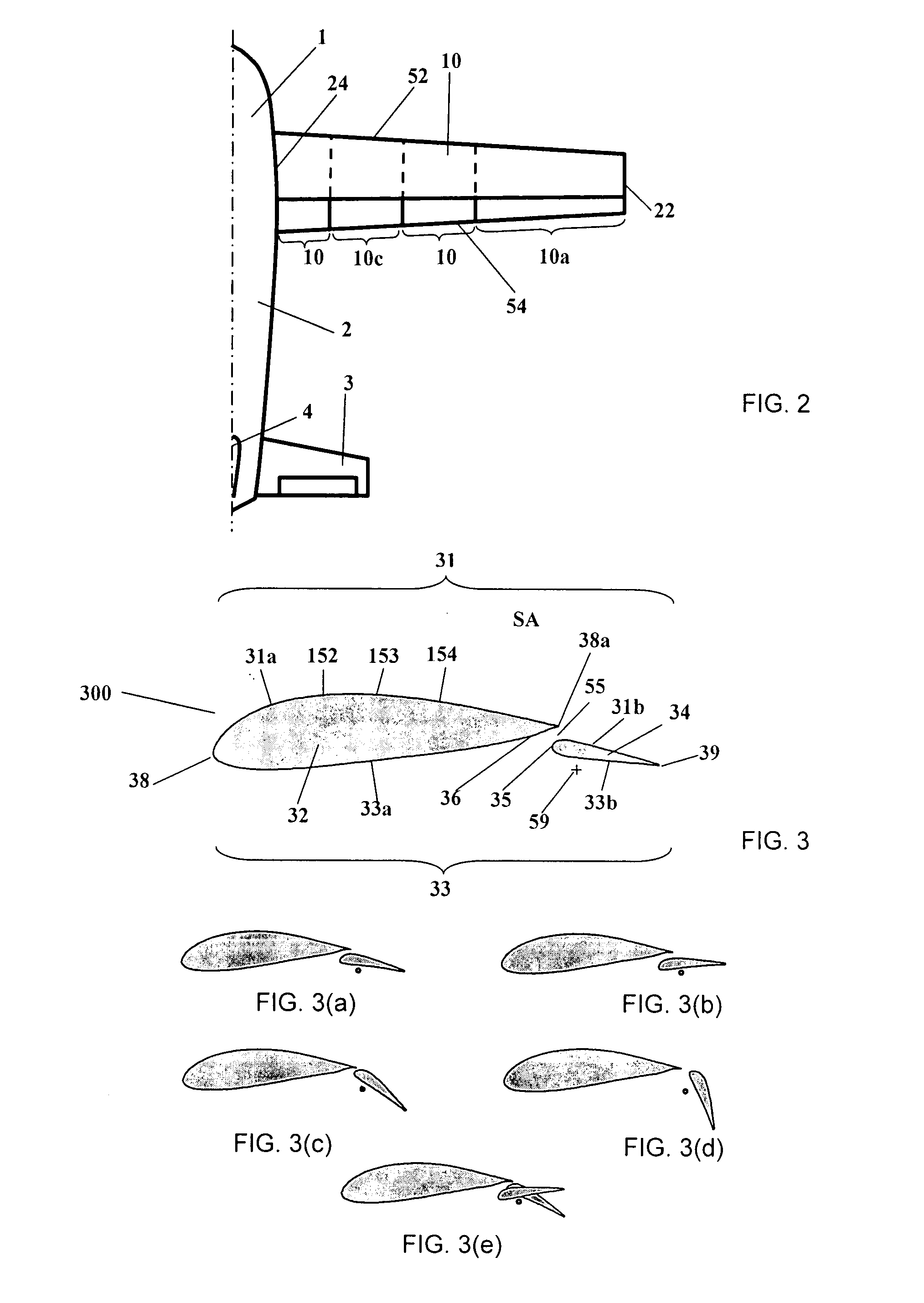
[0079]According to a first embodiment of the invention, high lift wings are provided for aircraft, in particular fixed wing aircraft. For the purpose of example, and referring to FIG. 2, such an aircraft is described herein as a fixed-wing aircraft, generally designated with reference numeral 1, comprising a regular subsonic / transonic configuration, having a fuselage section 2, main wings 10 (only the starboard wing (also referred to herein as a “wing half”) is illustrated in this figure), tailplane 3, vertical stabilizer 4, and a propulsion system (not shown). However, the present invention is also applicable, mutatis mutandis, to other types of aircraft, for example: gliders; subsonic / transonic aircraft having canards rather than a tailplane; general aviation aircraft, cruise missiles or other air delivered ordinance, and so on. Furthermore, while the present invention finds particular application in UAV aircraft, the invention may also be applied to manned aircraft, mutatis mutan...


PUM


Abstract

A slotted aerofoil configuration is provided in which the leading element thereof is contoured to provide mild stall characteristics. A wing based partially or fully on such an aerofoil, an air vehicle including such wings, and a method for designing an aerofoil are also disclosed

Description

[0001]This application claims the benefit of prior U.S. provisional patent application No. 60 / 808,957 filed date May 30, 2006, the contents of which are hereby incorporated by reference in their entirety.FIELD OF THE INVENTION[0002]This invention relates to aerofoil and wing configurations for aircraft, in particular to high-lift aerofoils and wings therefor.BACKGROUND OF THE INVENTION[0003]In many types of aircraft, particularly fixed wing aircraft, it is standard practice to avoid flying, under aerodynamically generated lift, at velocities close to stall airspeeds. This practice is even more strictly adhered to in the case for unmanned air vehicles (UAV), and improves safety and minimizes risk of loss or damage to the air vehicles, which can occur when losing aerodynamic control thereof.[0004]However, this practice also results in a restriction in the operation of the air vehicle, particularly UAV's, to above a specified airspeed (which includes a speed safety margin imposed on st...

Claims


Application Information

Patent Timeline
Patent Type & Authority Applications(United States)
IPC IPC(8): B64C9/32
CPCB64C9/18B64C3/14
Inventor SHEPSHELOVICH, MICHAELNAGEL, ALEX
Owner ISRAEL AEROSPACE IND
Why Eureka
Try Eureka