Magnetic resonance imaging system with a class-e radio frequency amplifier

a radio frequency amplifier and magnetic resonance imaging technology, applied in wave based measurement systems, instruments, and reradiation, etc., can solve the problems of increased power dissipation, low amplifier efficiency, and high temperature in the scanner

Inactive Publication Date: 2007-12-06
KENERGY INC
View PDF17 Cites 30 Cited by
  • Summary
  • Abstract
  • Description
  • Claims
  • Application Information

AI Technical Summary

Benefits of technology

[0018] For a volume type transmit coil, a separate Class-E amplifier is connected to drive each rung. In this case, the radio frequency section preferably further comprises a drive circuit and a power splitter. The drive circuit modulates the radio frequency carrier signal with the control signal to produce a drive signal. The power splitter divides the drive signal into a plurality of sub-drive signals one of which for each rung of the transmit coil

Problems solved by technology

Unfortunately, these properties also increase the power dissipation and thus cause higher temperatures in the scanner.
Unfortunately, these amplifiers are not very efficient and produce a significant amount of heat.
A Class-A amplifier has very good linearity, but this type of amplifier is less than 10% efficient, therefore its power consumption is relatively high.
This type

Method used


Image

  • Magnetic resonance imaging system with a class-e radio frequency amplifier
  • Magnetic resonance imaging system with a class-e radio frequency amplifier
  • Magnetic resonance imaging system with a class-e radio frequency amplifier

Examples


Embodiment Construction

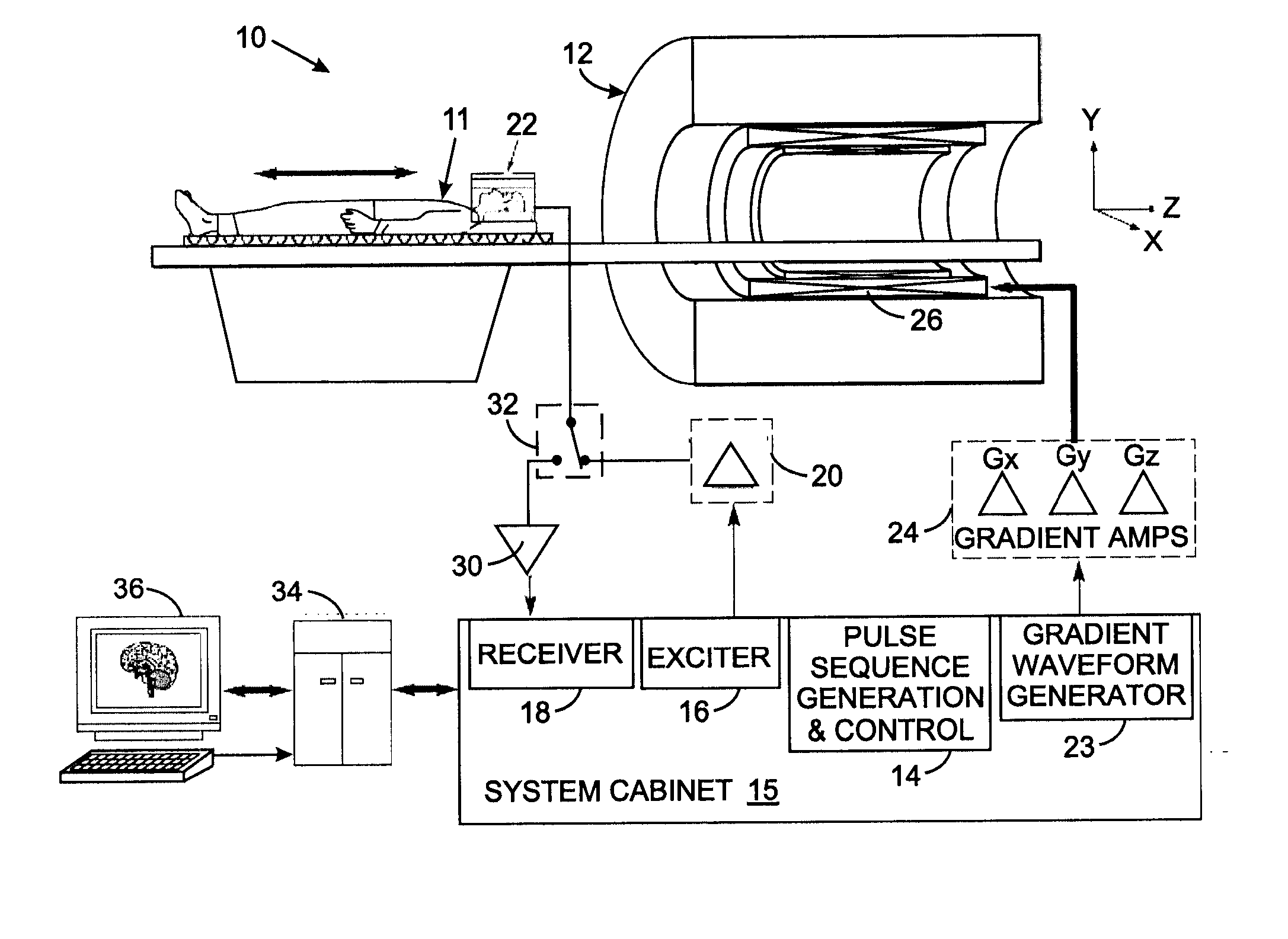
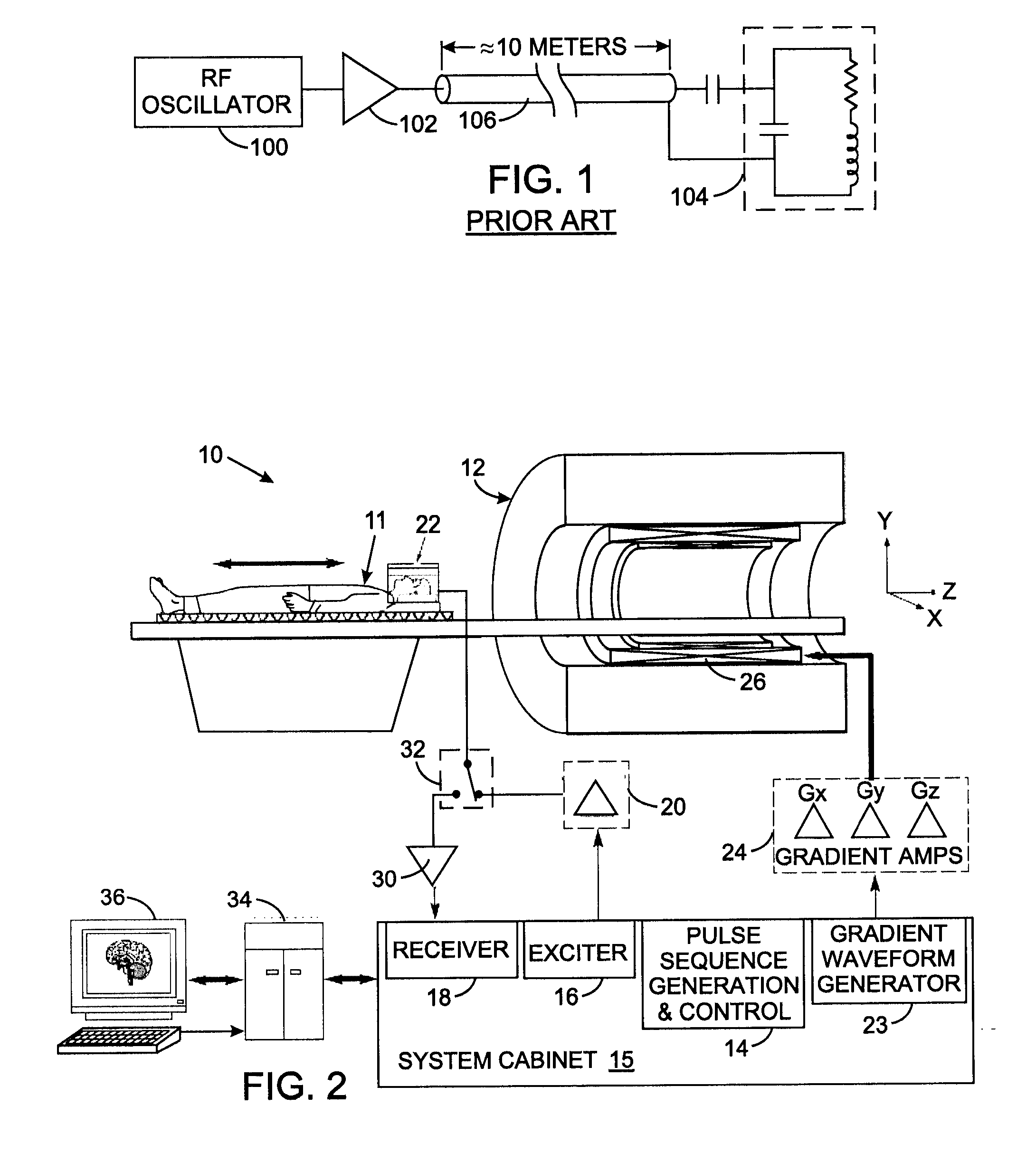
[0033] With initial reference to FIG. 2, an imaging scan in an MRI system 10 commences with the patient 11 being prepared by a technologist who is responsible for patient safety and placement of a transmit / receive local coil 22 on the patient. Once the landmark (origin of the scan location) is set and the patient 11 positioned inside the scanner 12, the prescribed protocol is entered into the processor 34. The protocol is a set of parameters for the imaging pulse sequence being prescribed. When the protocol is loaded, the pulse sequence generation and control unit 14 in the system cabinet 15 specifies the magnetic field gradient and radio frequency (RF) waveforms and prepares the system 10 for data acquisition. The X, Y, and Z magnetic field gradient waveforms produced by generator 23 are amplified by the gradient amplifiers 24 (also known as “gradient drivers”) and fed to the gradient coils 26 in accordance with the waveforms prescribed by the current protocol.

[0034] The RF subsys...


PUM


Abstract

A Class-E amplifier has bee adapted for use in the radio frequency section of a magnetic resonance imaging (MRI) system. A drive signal is produces by modulating the envelope of a radio frequency carrier signal and then applied to a switch in the Class-E amplifier. The switch is connected in series with a choke between a supply voltage terminal and circuit ground with an output node formed between the choke and the switch. The output node is coupled to circuit ground by a shunt capacitor. In a preferred embodiment, a pair of such amplifiers, that are Π radians out of phase, are connected to each rung of a transverse electromagnetic transmit array type radio frequency coil of the MRI system.

Description

CROSS-REFERENCE TO RELATED APPLICATIONS [0001] This application claims benefit of U.S. Provisional Patent Application No. 60 / 776,855 filed Feb. 24, 2006.STATEMENT REGARDING FEDERALLY SPONSORED RESEARCH OR DEVELOPMENT [0002] Not Applicable BACKGROUND OF THE INVENTION [0003] 1. Field of the Invention [0004] The present invention relates to magnetic resonance imaging (MRI) scanners, which are used for non-invasive imaging of the internal organs of a patient for medical diagnostic purposes, and more particularly to a radio frequency amplifier for use with an MRI scanner. [0005] 2. Description of the Related Art [0006] Magnetic Resonance Imaging (MRI) is a well-known procedure based on nuclear magnetic resonance (NMR) principles for obtaining detailed, two and three dimensional images of patients. MRI is well suited for the imaging of soft tissues and is primarily used for diagnosing internal injuries. [0007] Typical MRI systems include a magnet capable of producing an intense, homogenou...

Claims


Application Information

Patent Timeline
IPC IPC(8): G01R33/32H03F3/217
CPCG01R33/34046G01R33/3614G01R33/3453G01R33/34076
Inventor BULKES, CHERIKDENKER, STEPHENBEUTLER, ARTHUR J.
Owner KENERGY INC
Why Eureka
Try Eureka