Radio frequency (RF) signal receiver using optical processing and associated methods

a radio frequency (rf) and signal receiver technology, applied in the field of wireless communication, can solve the problems of inherently band limited architecture, few dsp fpga's operating at these rates with manageable power dissipation, and the demand for wideband high data rate communications has outpaced the capabilities of analog receivers and dsp processors, so as to reduce sampling rate, increase collection bandwidth in this approach, and high data rate digital processing

Active Publication Date: 2007-12-06
ALCATEL LUCENT SAS +2
View PDF25 Cites 32 Cited by
  • Summary
  • Abstract
  • Description
  • Claims
  • Application Information

AI Technical Summary

Benefits of technology

[0027]Optical processing of the present approach avoids the need for high data rate digital processing and may reduce the sampling rate needed. The collection bandwidth in this approach is increased compared to the conventional DSP approach. For example, the approach is applicable to broadband phased array antennas, and supports both receive and transmit for communications and RADAR.

Problems solved by technology

The demand for wideband high data rate communications with spectral efficiencies greater than 1 bit / Second / Hertz has outstripped the capabilities of analog receivers and DSP processors.
Few DSP FPGA's operate at these rates with manageable power dissipation.
Architecture is inherently band limited due to VSWR effects and group delay as percent bandwidth increases.
Few DSP FPGA's operate at these rates with manageable power dissipation.

Method used


Image

  • Radio frequency (RF) signal receiver using optical processing and associated methods
  • Radio frequency (RF) signal receiver using optical processing and associated methods
  • Radio frequency (RF) signal receiver using optical processing and associated methods

Examples


Embodiment Construction

[0035]The present invention will now be described more fully hereinafter with reference to the accompanying drawings, in which preferred embodiments of the invention are shown. This invention may, however, be embodied in many different forms and should not be construed as limited to the embodiments set forth herein. Rather, these embodiments are provided so that this disclosure will be thorough and complete, and will fully convey the scope of the invention to those skilled in the art. Like numbers refer to like elements throughout.

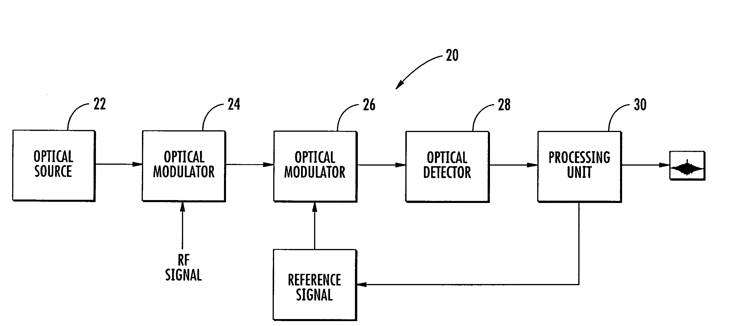
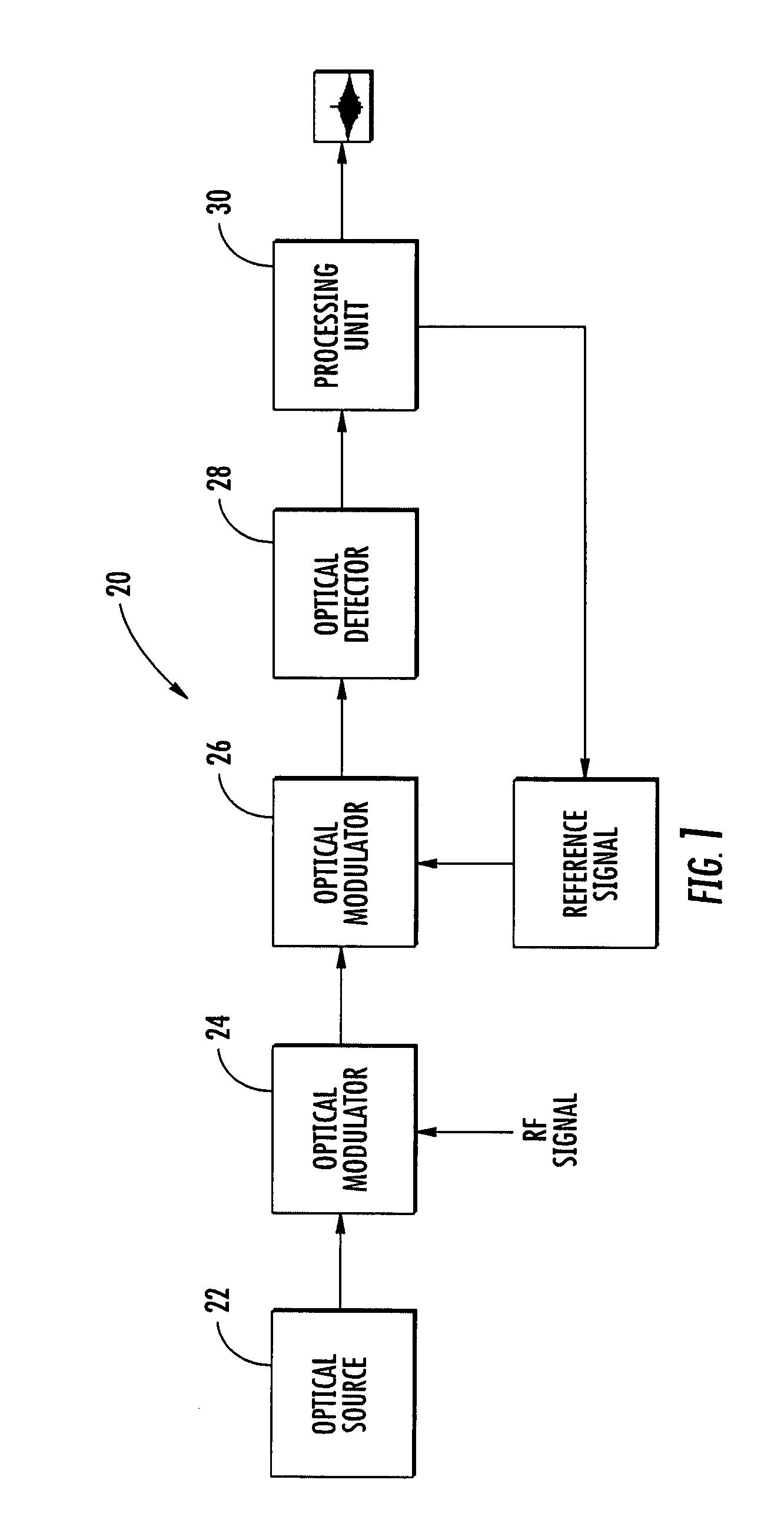
[0036]With reference to FIG. 1, a signal receiver 20, such as an RF matched filter receiver, using optical techniques will be described. The RF matched filter receiver 20 provides a cross-correlation between two signals such as an RF signal (e.g. a received RADAR signal) and a reference signal (e.g. a copy of the transmit RADAR signal). The receiver 20 includes an optical source 22 (typically a laser) that produces a continuous waveform or pulsed (e.g. fro...


PUM


Abstract

A signal receiver, such as an RF-matched filter receiver, includes an optical source (e.g. a mode-locked laser) providing an optical signal, and a first optical modulator to modulate the optical signal with a received RF signal and provide a modulated optical signal. A second optical modulator modulates the modulated optical signal with a reference signal and provides a twice modulated optical signal. The modulators may be Mach-Zehnder Modulators (MZM) and/or Indium Phosphide (InP) modulators. An optical detector receives the twice modulated optical signal and provides a detected signal, and a processing unit receives the detected signal and extracts or measures cross-correlation between the received RF signal and the reference signal.

Description

CROSS-REFERENCE TO RELATED APPLICATION[0001]The present application claims priority to U.S. Provisional Application Ser. No. 60 / 803,460 filed May 30, 2006 the entire disclosure of which is incorporated by reference herein.FIELD OF THE INVENTION[0002]The present invention relates to the field of communications, and, more particularly, to wireless communications and related methods.BACKGROUND OF THE INVENTION[0003]This section discusses aspects that may be helpful to facilitating a better understanding of the inventions. Accordingly, the statements of this section are to be read in this light. The statements of this section are not to be understood as admissions about what is in the prior art or what is not in the prior art.[0004]The demand for wideband high data rate communications with spectral efficiencies greater than 1 bit / Second / Hertz has outstripped the capabilities of analog receivers and DSP processors.[0005]For example, GSM cellular telephony devices represent the maximum si...

Claims


Application Information

Patent Timeline
Patent Type & Authority Applications(United States)
IPC IPC(8): H04B10/04
CPCH01Q3/2676H04B10/25752H04B10/1125
Inventor FITZGERALD, BRUCEDESALVO, RICHARDCHEN, YOUNG KAILEVEN, ANDREASDELFYETT, PETER J.
Owner ALCATEL LUCENT SAS
Why Eureka
Try Eureka