Method of manufacturing a modular damper

a manufacturing method and damper technology, applied in the field of dampers, can solve the problems of oem scrapping, adverse damping characteristics of dampers, and the same problem applies to damper base valves, etc., to achieve the effect of increasing handling, small equipment, and increasing profitability

Inactive Publication Date: 2007-12-13
RIDE CONTROL
View PDF9 Cites 2 Cited by
  • Summary
  • Abstract
  • Description
  • Claims
  • Application Information

AI Technical Summary

Benefits of technology

[0007] Therefore, what is needed is a more modular damper design that reduces the number components stocked for different dampers. Also, what is needed is a method of manufacturing low volume dampers more efficiently. SUMMARY OF THE INVENTION AND ADVANTAGES
[0012] The manufacture of subassemblies, for example by using the method and apparatus described above, enables OEMs to cost effectively manufacture small lot size dampers. The subassemblies are manufactured at the OEM's main facility that manufactures the large lot size dampers. However, subassemblies are also shipped to another OEM facility that is located in close proximity to the customer, for assembly into small lot size dampers. The second OEM facility, in one example, is mobile trailers located on the customer's property, for example in the customer's parking lot. The subassemblies arrive at the second OEM facility pretested and are assembled into dampers in response to a build request from the customer facility. Despite the smaller equipment and increased handling at the second OEM facility, the OEM is able to produce the small lot sizes more profitably than contracting the small lot sizes out while quickly satisfying the customer's build needs.
[0013] Accordingly, the above mentioned provides a modular damper design that reduces the number of components stocked for different dampers while providing consistent loading of the piston valve assembly.

Problems solved by technology

This same problem applies to damper base valves and other damper subassemblies.
The damping characteristics of the damper are adversely affected if the deflection discs are not properly loaded against the piston.
One problem is that it may difficult to consistently control the predetermined torque resulting in failure of the finally assembled damper during its final test, which results in scrap at the OEM.
Moreover, the load on the deflection discs may decrease even after the predetermined torque has successfully been achieved and the damper has passed the final test.
Another problem with the proliferation of damper components is that it is difficult to manufacture low volume dampers cost effectively.
OEMs typically can only efficiently build dampers in large lot sizes.
As a result, the OEMs have contracted with outside companies to build the unprofitable smaller lots.

Method used


Image

  • Method of manufacturing a modular damper
  • Method of manufacturing a modular damper
  • Method of manufacturing a modular damper

Examples


Embodiment Construction

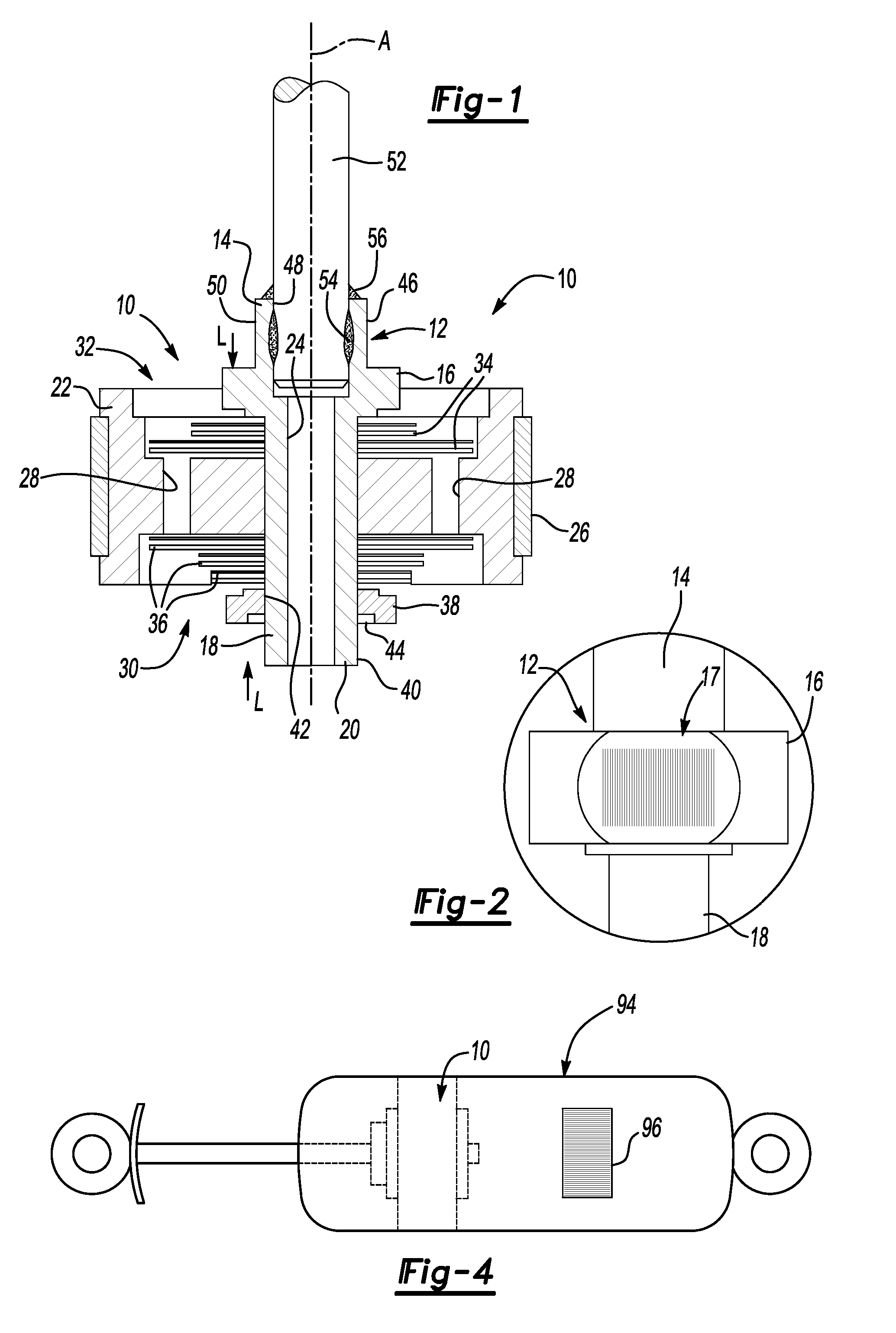
[0020] A piston valve assembly 10 of the present invention is shown in FIG. 1. The assembly 10 includes an inventive hub 12 that is designed to be used with different sized pistons and deflection discs to facilitate a more modular damper assembly. The hub 12 includes a first end 14 that is adapted to receive a piston rod. The first end 14 includes a shoulder 16 and a neck 18 extending from the shoulder 16 to a second end 20. The hub 12 is preferably marked with identifying information 17, for example by laser etching a bar code, that may be indicative of the components that will be installed on the hub 12 that will provide the particular piston valve assembly configuration, as shown in FIG. 2.

[0021] A piston 22 having a hole 24 is installed onto the hub 12 with the neck 18 received in the hole 24. Different sized pistons may be used on the same hub, for example, 25 mm, 30 mm, or 35 mm diameter pistons having the same sized central hole 24 could fit on the same hub. The neck 18 has ...


PUM

PropertyMeasurementUnit
diameteraaaaaaaaaa
diameteraaaaaaaaaa
diameteraaaaaaaaaa

Abstract

A piston valve assembly for a damper comprises a piston having a central hole and a fluid passageway spaced from the hole. A deflection disc having a central aperture is aligned with the hole. A hub, common across different dampers, includes a neck that is arranged in the hole and the aperture of the deflection disc. A retainer abuts an unthreaded outer surface of the hub. During assembly, the retainer is received on the cylindrical outer surface in a slip fit relation and secured to the hub under a predetermined clamp load. Throughout the manufacturing process, components of the piston valve assembly are marked with identifying information that may be compared to other identifying information on the piston assembly throughout the manufacturing process to ensure integrity of the piston valve assembly. The piston valve assembly and other assemblies can be sent to another OEM facility near the customer to manufacture dampers that satisfy build requests for low volume dampers.

Description

BACKGROUND OF THE INVENTION [0001] This application is a divisional application of U.S. Ser. No. 10 / 894,442, filed on Jul. 19, 2004.[0002] This invention relates to dampers such as vehicle suspension shock absorbers, struts and the like. More particularly, the invention relates to a common hub design for piston valve arrangements enabling a more modular damper. [0003] Dampers such as shock absorbers and struts are used in vehicles to absorb inputs from the roadway to provide a desirable vehicle ride. Typically, vehicle dampers employ a piston that moves through a cylinder having hydraulic fluid. The fluid flows through fluid passageways and valves in the piston, which absorbs the roadway inputs in the form of heat. The piston size, valves, and piston rod are selected based upon the particular vehicle and vehicle application, which requires the damper OEM to stock numerous parts for different vehicles and even for different suspension packages for the same vehicle. [0004] One common ...

Claims


Application Information

Patent Timeline
Patent Type & Authority Applications(United States)
IPC IPC(8): B21K1/20
CPCF16F9/3271G05B19/41805G05B2219/31044Y10T29/49828Y10T29/49771Y10T29/49412G05B2219/32025Y02P90/02
Inventor CARLSTEDT, ROBERT P.SIESEL, JAMES J.SLEDZ, CHRISTOPHER T.
Owner RIDE CONTROL
Why Eureka
Try Eureka