

Cryopump and semiconductor device manufacturing apparatus using the cryopump
a semiconductor device and manufacturing apparatus technology, applied in lighting and heating apparatus, positive displacement liquid engines, separation processes, etc., can solve the problem of no longer being able to discharge, and achieve the effect of reducing the working time reducing the cost of a semiconductor device manufactured by and increasing the productivity of the semiconductor device manufacturing apparatus
- Summary
- Abstract
- Description
- Claims
- Application Information
AI Technical Summary
Benefits of technology
Problems solved by technology
Method used
Image

Examples
first embodiment
[0029]FIG. 3 is a cut-away side view of a cryopump according to a first embodiment of the present invention.
[0030]As shown in FIG. 3, a cryopump 10 according to the first embodiment of the present invention includes a cryopump main body 11 connected to a vacuum chamber 30 whose inside gas is discharged via an inlet 12a. The cryopump main body 11 includes a vacuum container 12. The vacuum container 12 includes a shielding section 14, a cryogenic cooler 20, a baffle 15, a first cryopanel 16, and second cryopanels 16′. The vacuum container 12 provides a thermometer (not shown) for measuring temperatures of the shielding section 14, the baffle 15, the first cryopanel 16, and the second cryopanels 16′, and a safety valve (not shown) which discharges gas inside the vacuum container 12 to the outside when inside pressure of the vacuum container 12 becomes excessively high.
[0031]The vacuum container 12 is formed of a metal material such as stainless steel. One end of the vacuum container 12...
first modified example of first embodiment
[0049]Next, a first modified example of the first embodiment of the present invention is described. In the first modified example of the first embodiment of the present invention, the shape of the first cryopanel is different from that shown in FIG. 3. The others are the same as those in the first embodiment of the present invention. Therefore, the same description is omitted.
[0050]FIG. 7 is a cut-away side view of a cryopump 40 according to the first modified example of the first embodiment of the present invention.
[0051]As shown in FIG. 7, in the cryopump 40, a first cryopanel 41 and second cryopanels 41′ are disposed. The first cryopanel 41 located at a position nearest to the baffle 15 provides a top section 41a and a flat surface 41c. The flat surface 41c extends in the outside direction from the top section 41a and the rim part of the flat surface 41c is bent in the downward direction. In the first modified example, the first cryopanel 41 located at the position nearest to the...
second modified example of first embodiment
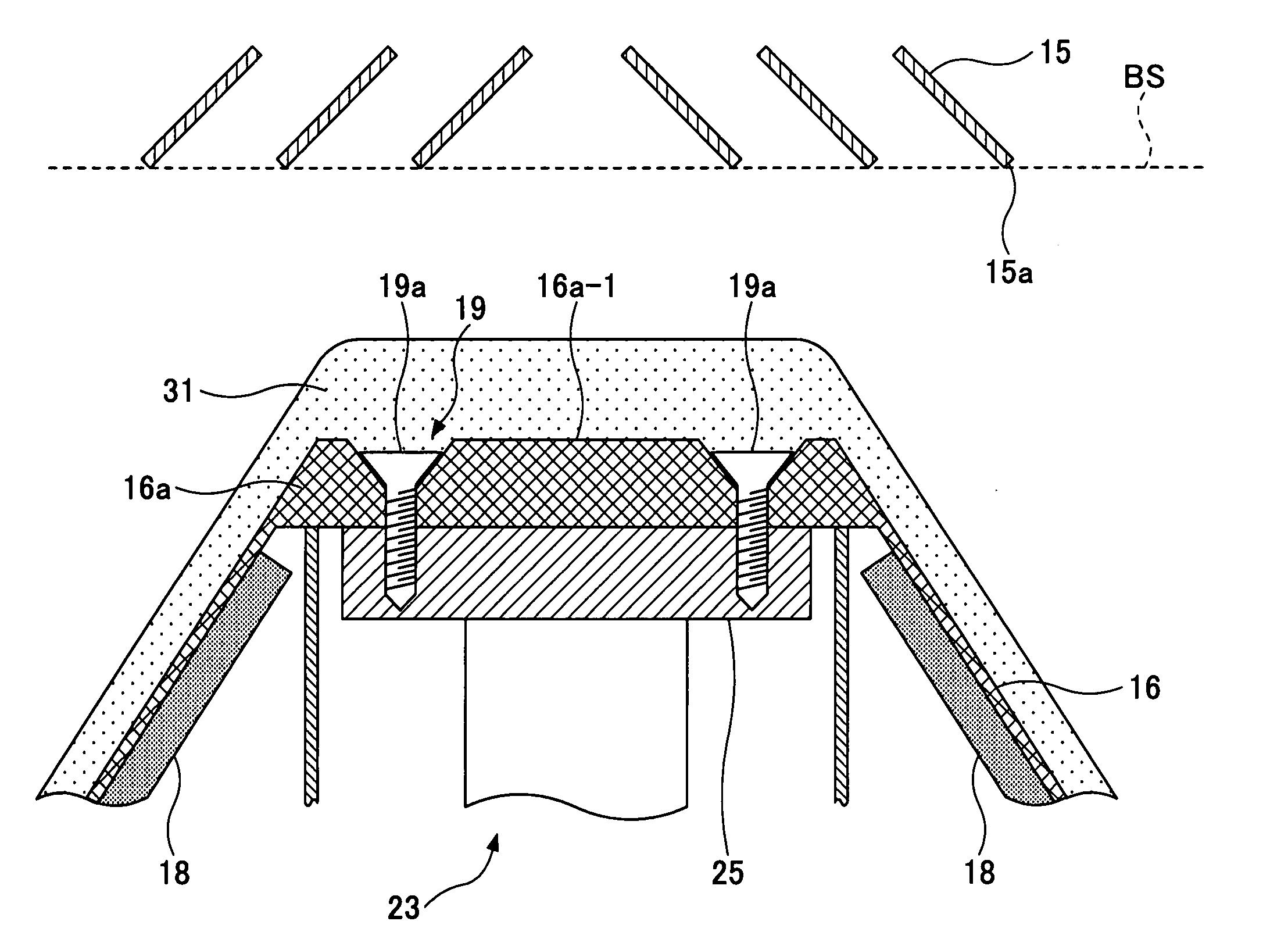
[0057]Next, a second modified example of the first embodiment of the present invention is described. In the second modified example, the shape of a first cryopanel located at a position nearest to the baffle surface BS is different from that shown in FIG. 7 and also a securing method of the first cryopanel to the second cooling stage 25 is different from that shown in FIG. 7. The others are the same as those in the first modified example of the first embodiment of the present invention.
[0058]FIG. 8 is a cut-away side view of a cryopump 50 according to the second modified example of the first embodiment of the present invention. FIG. 9 is an enlarged cut-away side view of a part of the cryopump 50 where a first cryopanel 51 and the baffle 15 exist.
[0059]As shown in FIGS. 8 and 9, in the cryopump 50, the first cryopanel 51 located at the position nearest to the baffle surface BS provides a concave section (top section) 51a and a flat surface 51c. The first cryopanel 51 is secured to t...
PUM
| Property | Measurement | Unit |
|---|---|---|
| thickness | aaaaa | aaaaa |
| depth | aaaaa | aaaaa |
Abstract
Description
Claims
Application Information